DEMM9SX-A101 查看數據表(PDF) - ITT Cannon
零件编号
产品描述 (功能)
生产厂家
DEMM9SX-A101 Datasheet PDF : 62 Pages
| |||
Military/Hi-Reliability D*M D-Subminiature
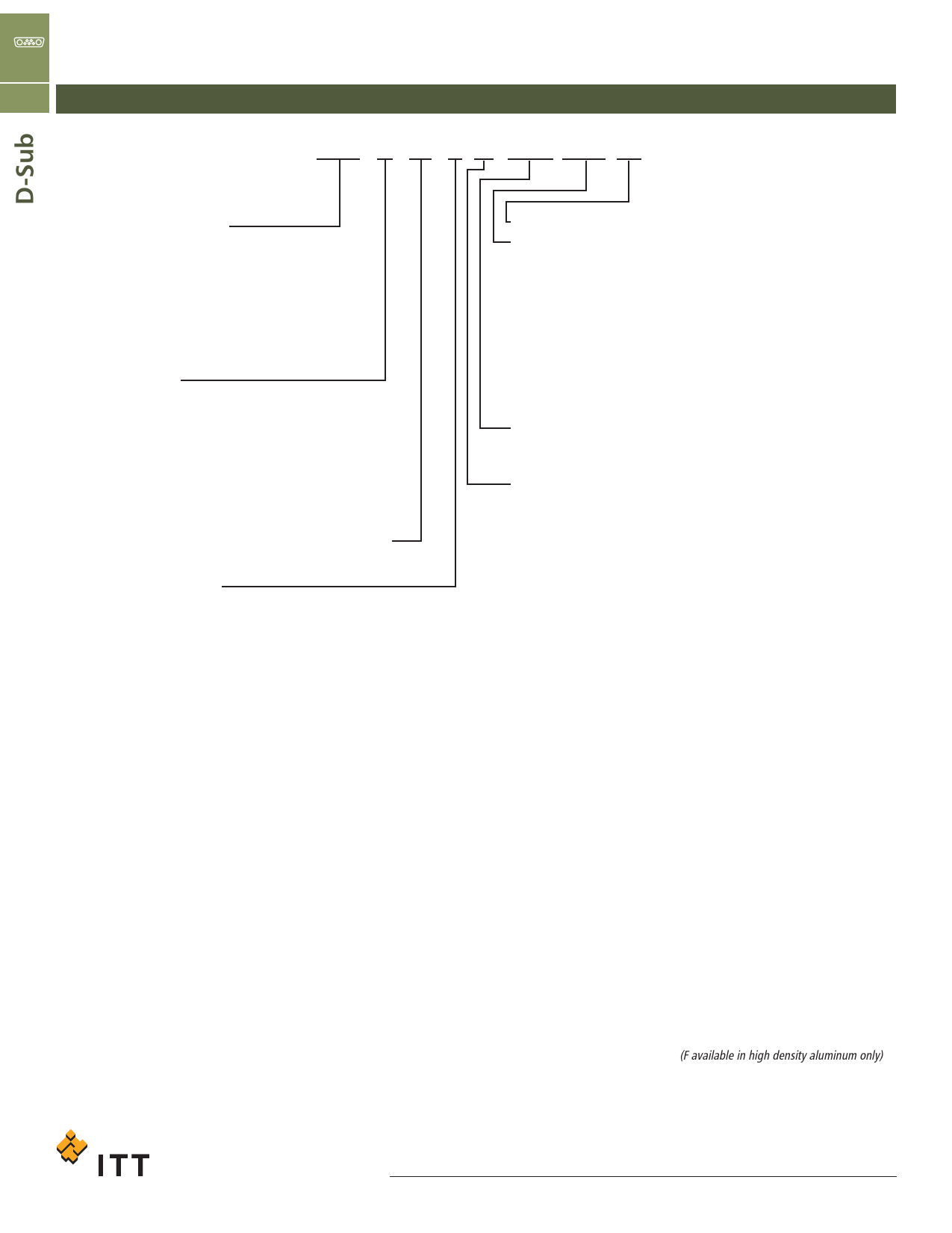
Ordering Information - Connector Designator
C For Hi-Reliability Crimp, Solder Cup and PCB Type, Standard & Hi-Density Connectors with Machined Contacts
Typical Part Number:
DBM* E 25 P M NMB A197 FO
• Product Family Designator
D*M = Solder Cup & Std. Density PCB
Industrial/Commercial Version
D*MM = Solder Cup & PCB Mil version
(50 micro-inch gold contact/plating)
D*MA = Crimp & Hi-Density PCB Industrial/
Commercial Version
D*MAM =
Crimp/Hi-Density PCB Mil version
(50 -in gold contact plating)
• Hardware Modifier
=0.120” (3,05mm) Through Hole
B =4-40 Female Screwlock
E =4-40 Clinchnut
K =0.162” (4,11mm) Through Hole
X =M3 clinchnut
Y =Dual Float Mount
* =Shell Sizes are E, A, B, C, D
• Layouts *Standard Density (D*M, D*MM) 9, 15, 25, 37, 50
*High Density (D*MA, D*MAM) 15, 26, 44, 62, 78, 104
• Gender P = Male Plug, Pin
S = Female Receptacle, Socket
FO - Without contacts - D*MA crimp versions only
• Modifier (standard)
Yellow chromate over zinc shells
A197
Tin over Nickel shells (receptacles only) (RoHS)
F224
Epoxy sealing of insulator to shell and contacts
F225
303 Stainless steel, passivated
(Non Hardware Versions Only)
K52
50 gold over copper plating on shells and contacts
K87
Tin, dimpled shells (plugs only) (RoHS) (US only)
K128
K52 gold plating on Aluminum Shells, Nickel Under Plate
F216
Machined Aluminum Shells, Nickel Under Plate
A101
Yellow chromate over cadmium
• Residual Magnetism/Outgassing
NMB- 200 Gamma Max. Residual Magnetism/<1% TML
• PC Tail Modifier (Standard Density)
= Solder cup (D*M/D*MM)
A = 90° PCB contact w/Plastic Bracket (.127" lg by .040" Ø)
B = Straight PCB contact w/spacer (.127" lg by .040" Ø)
C = 90° PCB contact w/o Plastic Bracket (.127" lg by .040" Ø)
D = 90° PCB contact w/Plastic Bracket (.127" lg by .030" Ø)
E = Straight PCB contact w/spacer (.127" lg by .030" Ø)
F = 90° PCB contact w/o Plastic Bracket (.127" lg by .030" Ø)
G = 90° PCB contact w/Plastic Bracket (.158" lg by .040" Ø)
H = Straight PCB contact w/spacer (.158" lg by .040" Ø)
K = 90° PCB contact w/o Plastic Bracket (.158" lg by .040" Ø)
L = 90° PCB contact w/Plastic Bracket (.158" lg by .030" Ø)
M = Straight PCB contact w/spacer (.158" lg by .040" Ø)
P = 90° PCB contact w/o Plastic Bracket (.158" lg by .030" Ø)
R = 90° PCB contact w/o Plastic Bracket (.183" lg by .030" Ø)
S = 90° PCB contact w/Plastic Bracket (.183" lg by .030" Ø)
W = 90° PCB contact w/Plastic Bracket (.183" lg by .040" Ø)
X = Straight PCB contact w/spacer (.183" lg by .030" Ø)
Z = Straight PCB contact w/spacer (.183" lg by .040" Ø)
F179 = Straight square PCB or wire wrap contact (.375" by .024")
F179A = Straight square PCB or wire wrap contact (.500" by .024")
**L = 90° PCB contact w/Plastic Bracket (.140" lg by .021" Ø)
**M = Straight PCB contact w/Spacer (.140" lg by .021" Ø)
**P = 90° PCB contact w/o Plastic Bracket (.140" lg by .021" Ø)
R = 90° PCB contact w/o Plastic Bracket (.197" lg by .021" Ø)
S = 90° PCB contact w/Plastic Bracket (.197" lg by .021" Ø)
Z/OL3 = Straight PCB contact w/Spacer (.197" lg by .021" Ø)
* 104 Position Available in Machined Aluminum Shells only
* = Crimp (D*MA, D*MAM)
* = Shell Sizes are E, A, B, C, D, F (F available in high density aluminum only)
** = Legacy Tail Modifiers “D”, “E” and “F” have been replaced by Tail Modifiers
“L”, “M” and “P” respectively.
Dimensions shown in inches (mm)
Specifications and dimensions subject to change
www.ittcannon.com
C-8
Share Link: 