HT82M33A 查看數據表(PDF) - Holtek Semiconductor
零件编号
产品描述 (功能)
生产厂家
HT82M33A Datasheet PDF : 13 Pages
| |||
HT82M33A
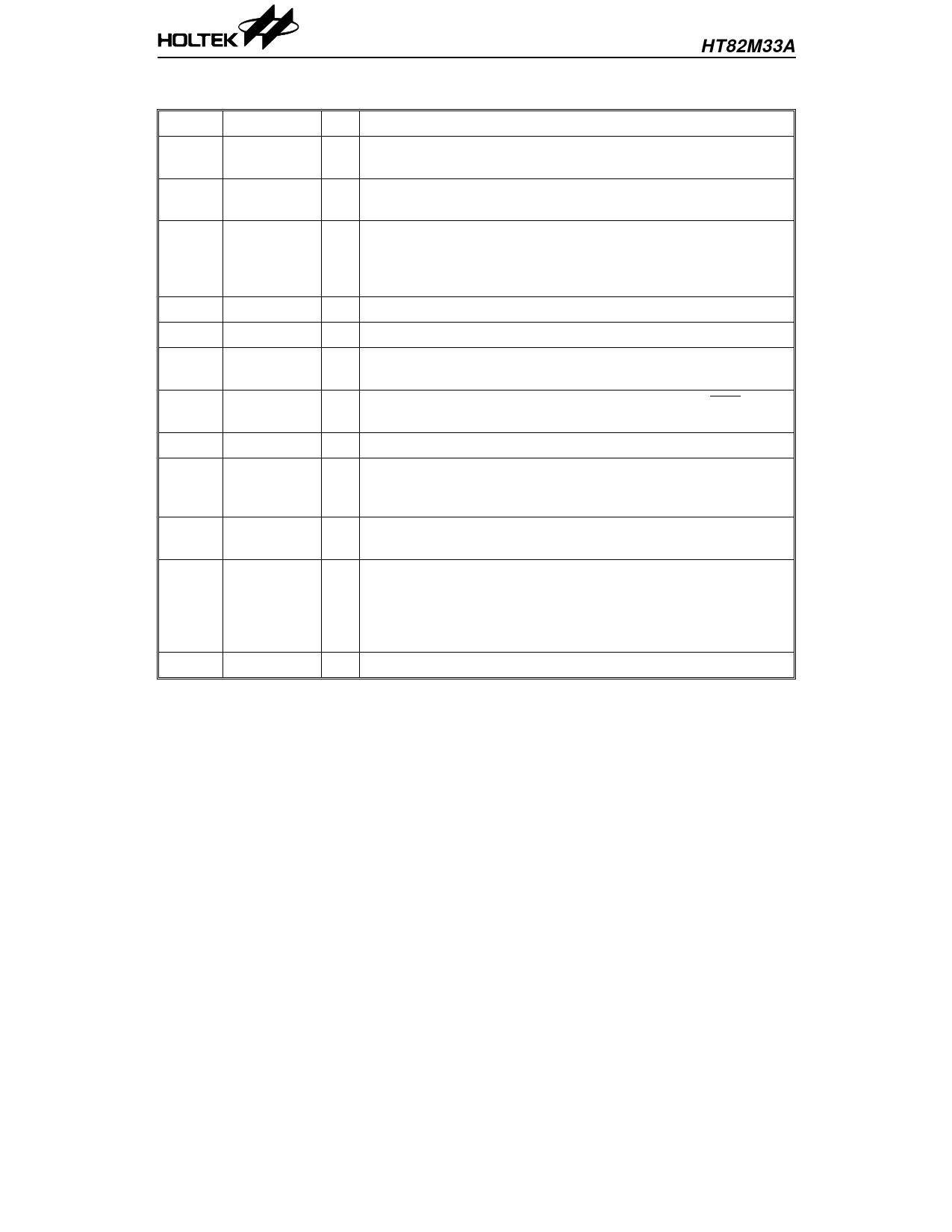
Pin Description
Pin No. Pin Name
1,2
Z1, Z2
3
RESET
4
MODE
5
OSCI
6
OSCO
7
CLOCK
8
DATA
9
VSS
10~12 RB, Ro, LB
13~16
X1, X2,
Y1, Y2
17
TEST
18
VDD
I/O
Description
I
“Z axis input”: Supports two kinds of scroller input, optomechanical
and mechanical
I
“Reset input”: Resets internal circuit by input low, normal is
connected to high by internal pull-high resistor (120kΩ).
“MS or PS/2 mode selection”: Low for PS/2 mouse, high for MS
I
mouse. The MS PnP mouse ID code sure will appear when this pin
rise from low to high. Normal is connected to low by internal
pull-low resistor (60kΩ). The mode input transition voltage is 2.0V.
I “Oscillator in”: Connect to 2MHz crystal or resonator
O “Oscillator out”: Connect to 2MHz crystal or resonator
I/O
“CLOCK I/O”: PS/2 mouse CLOCK line. NMOS open drain output
with 7.5kΩ pull-high resistor.
I/O
“DATA/RXD I/O” PS/2 mouse DATA line or MS mouse RXD output.
NMOS open drain output with 7.5kΩ pull-high resistor.
I Negative power pin
“Right Button”: Normal pull-high (45kΩ), press connect to low.
I “Rolling Button” : Normal pull-high (45kΩ), press connect to low.
“Left Button”: Normal pull-high (45kΩ), press connect to low.
I
“X/Y axis input”: Auto level detecting input. Any signal over 0.6V
VPP is acceptable but the +VP cannot be over 2.5V
“IC test pin”: with built-in pull-low resistor. In normal operation
this is connected to VSS or floating. While the pin is connected to
I VDD, this will provide the H/W test. The chip will accord the state
of the RB pin, to switch the X1/Y1 and X2/Y2 via the PIN Ro and
LB output.
I Positive power pin.
Absolute Maximum Ratings
Supply Voltage ..............................–0.3V to 6.5V
Input Voltage................. VSS–0.3V to VDD+0.3V
Storage Temperature................. –50°C to 125°C
Operating Temperature............... –25°C to 70°C
Note: These are stress ratings only. Stresses exceeding the range specified under “Absolute Maxi-
mum Ratings” may cause substantial damage to the device. Functional operation of this device
at other conditions beyond those listed in the specification is not implied and prolonged
exposure to extreme conditions may affect device reliability.
2
3rd Mar ’99
Share Link: 