EL7520ILZ-T7 查看數據表(PDF) - Intersil
零件编号
产品描述 (功能)
生产厂家
EL7520ILZ-T7 Datasheet PDF : 18 Pages
| |||
EL7520, EL7520A
VREF REFERENCE
GENERATOR
OSCILLATOR
SLOPE
COMPENSATION
OSC
GM
AMPLIFIER
Σ
VOLTAGE
AMPLIFIER
PWM
LOGIC
CONTROLLER
BUFFER
VIN
DRVB
ISIN
VBOOST
UVLO
COMPARATOR
SHUTDOWN
& STARTUP
CONTROL
CURRENT
AMPLIFIER
CURRENT LIMIT
COMPARATOR
CURRENT
LIMIT REF
GENERATOR
ISAD
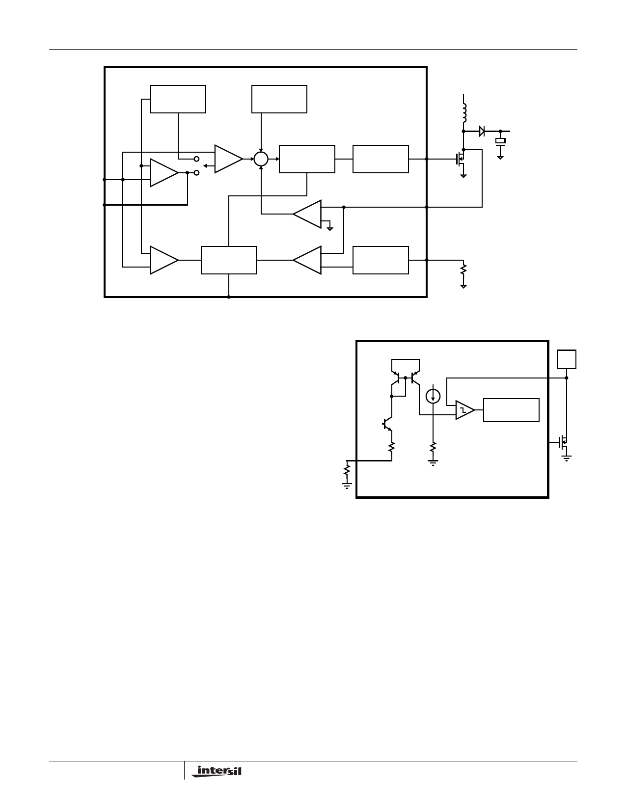
FIGURE 25. FUNCTION DIAGRAM OF THE BOOST CONTROLLER
The internal current limit circuitry is shown in Figure 26. The
circuit senses the voltage across the RDS(ON) when the
MOSFET is on; then compare it to the internal voltage
reference to realize the current limit. The internal voltage
reference is generated by a 10µA current and any additional
current set at ISAD pin flowing through an 8kΩ resistor. The
voltage reference is based on the following equation:
VTHRESHOLD
=
V-----I--S----A---D---
R1
+
10 µ A
× 8K
Where VISAD is the voltage at pin ISAD.
VISAD = VREF – VBE – 1K × ISAD
ISAD
=
V-----I--S---A----D---
R1
Where VBE ≈ 0.7V
The external resistor R1 should be chosen in the order of
100K to generate µA of current.
VDD
10µA
-
VREF
+
1K
8K
ISAD
R1
LX
ISIN
LOGIC
CONTROLLER
DRVB
FIGURE 26. CURRENT LIMIT BLOCK DIAGRAM
Hence the maximum output current is determined by the
following equation:
IOMAX
=
V-----T---H-----R----E----S----H----O----L----D--
RDSON
– -∆--2--I--L-
×
V-----I--N--
VO
Where ∆IL is the peak to peak inductor ripple current, and is
set by:
∆IL
=
-V----I--N-- × -D---
L fS
fS is the switching frequency; D is the duty cycle.
D
=
V-----O-----–-----V----I--N--
VO
11
FN7318.0
July 12, 2005
Share Link: 