FM24C04A 查看數據表(PDF) - Ramtron International Corporation
零件编号
产品描述 (功能)
生产厂家
FM24C04A Datasheet PDF : 12 Pages
| |||
FM24C04A
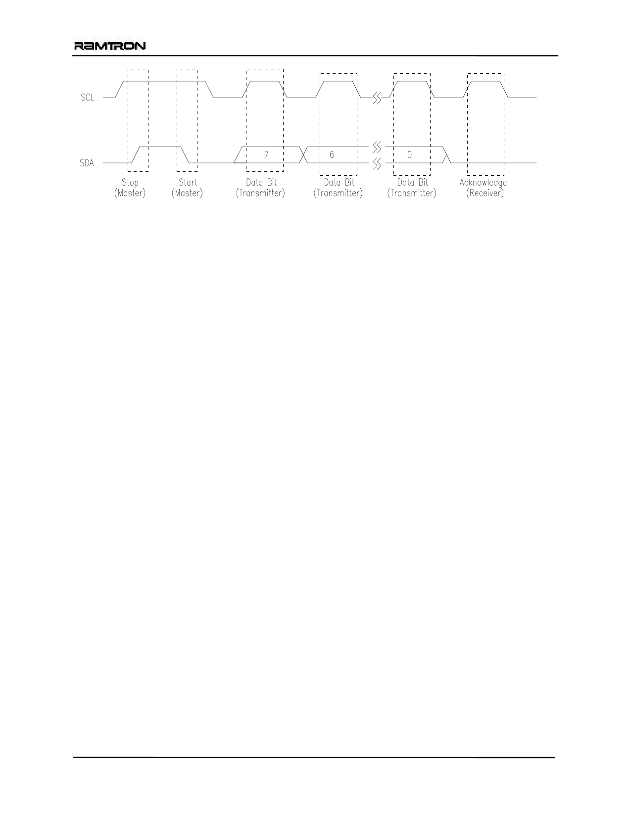
Figure 3. Data Transfer Protocol
Stop Condition
A Stop condition is indicated when the bus master
drives SDA from low to high while the SCL signal is
high. All operations must end with a Stop condition.
If an operation is pending when a stop is asserted, the
operation will be aborted. The master must have
control of SDA (not a memory read) in order to assert
a Stop condition.
Start Condition
A Start condition is indicated when the bus master
drives SDA from high to low while the SCL signal is
high. All read and write transactions begin with a
Start condition. An operation in progress can be
aborted by asserting a Start condition at any time.
Aborting an operation using the Start condition will
ready the FM24C04A for a new operation.
If during operation the power supply drops below the
specified VDD minimum, the system should issue a
Start condition prior to performing another operation.
Data/Address Transfer
All data transfers (including addresses) take place
while the SCL signal is high. Except under the two
conditions described above, the SDA signal should
not change state while SCL is high.
Acknowledge
The Acknowledge takes place after the 8th data bit has
been transferred in any transaction. During this state
the transmitter should release the SDA bus to allow
the receiver to drive it. The receiver drives the SDA
signal low to acknowledge receipt of the byte. If the
receiver does not drive SDA low, the condition is a
No-Acknowledge and the operation is aborted.
The receiver could fail to acknowledge for two
distinct reasons. First, if a byte transfer fails, the No-
Acknowledge ends the current operation so that the
device can be addressed again. This allows the last
byte to be recovered in the event of a communication
error. Second and most common, the receiver does
Rev. 3.0
Mar. 2005
not acknowledge the data to deliberately end an
operation. For example, during a read operation, the
FM24C04A will continue to place data onto the bus
as long as the receiver sends acknowledges (and
clocks). When a read operation is complete and no
more data is needed, the receiver must not
acknowledge the last byte. If the receiver
acknowledges the last byte, this will cause the
FM24C04A to attempt to drive the bus on the next
clock while the master is sending a new command
such as a Stop command.
Slave Address
The first byte that the FM24C04A expects after a
start condition is the slave address. As shown in
Figure 4, the slave address contains the device type,
the device select, the page of memory to be
accessed, and a bit that specifies if the transaction is
a read or a write.
Bits 7-4 are the device type and should be set to
1010b for the FM24C04A. The device type allows
other types of functions to reside on the 2-wire bus
within an identical address range. Bits 3-2 are the
device address. If bit 3 matches the A2 pin and bit 2
matches the A1 pin, the device will be selected. Bit
1 is the page select. It specifies the 256-byte block
of memory that is targeted for the current operation.
Bit 0 is the read/write bit. A 0 indicates a write
operation.
Word Address
After the FM24C04A (as receiver) acknowledges
the slave ID, the master will place the word address
on the bus for a write operation. The word address is
the lower 8-bits of the address to be combined with
the 1-bit page select to specify exactly the byte to be
written. The complete 9-bit address is latched
internally.
4 of 12
Share Link: 