GS175T48-15E 查看數據表(PDF) - STMicroelectronics
零件编号
产品描述 (功能)
生产厂家
GS175T48-15E Datasheet PDF : 10 Pages
| |||
GS120/175T48 FAMILY
USER NOTES
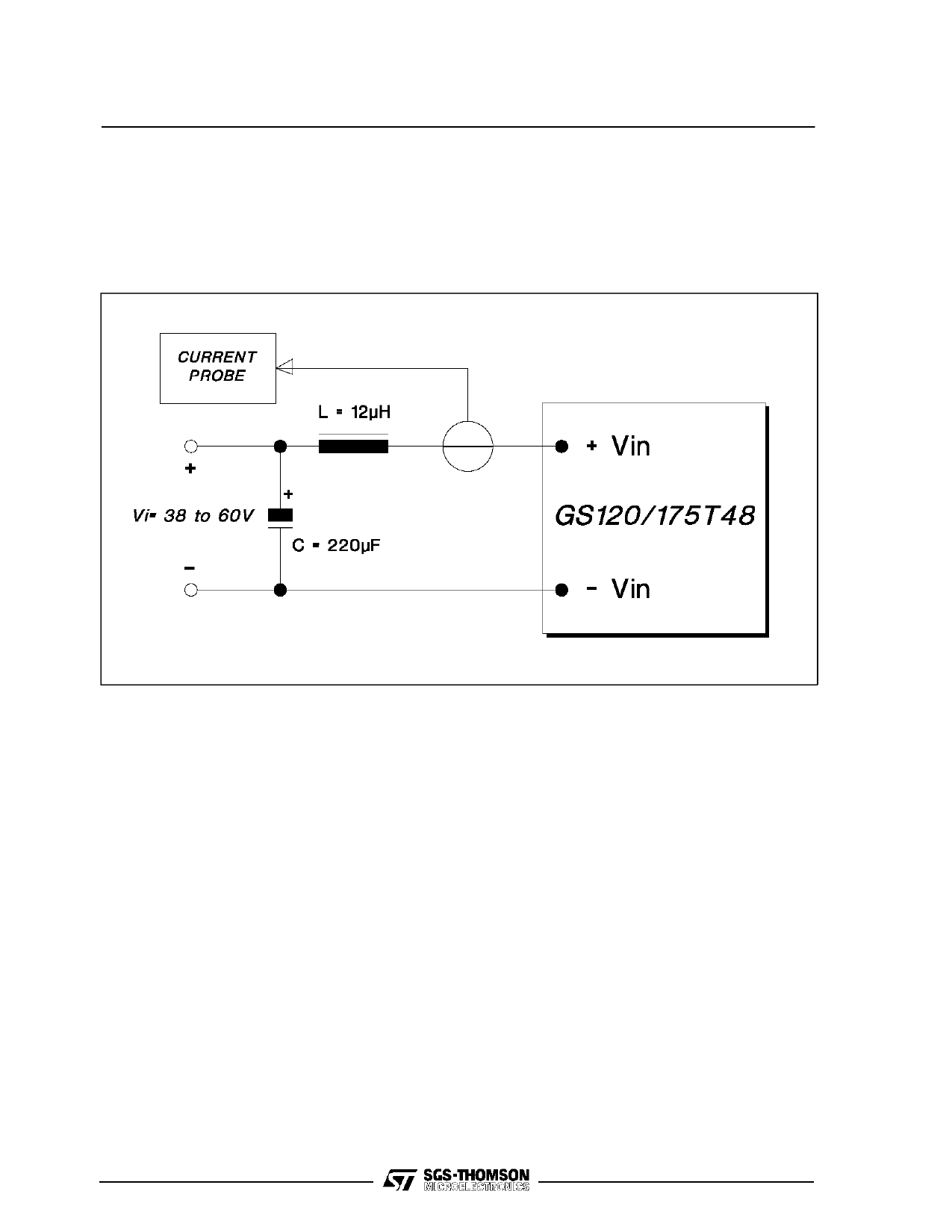
Reflected Input Current
The reflected input current measurement (lir, see Electrical Characteristics) is performed according to the
test set-up of fig. 2.
Figure 2.
Softstart
To avoid heavy inrush current the output voltage
rise time is 10ms maximum in any condition of load.
Remote Sensing
The remote voltage sense compensation range is
for a total drop of 0.6V equally shared between the
load connecting wires.
It is a good practice to shield the sensing wires to
avoid oscillations.
See the connection diagram on figures 3, 4, 5, 6.
Remote ON/OFF
The module is controlled by the voltage applied
between the ON/OFF pin and -IN pin.
The converter is ON (Enable) when the voltage
applied is lower than 1.2 V (see Vien on Electrical
Characteristics).
The converter is OFF (Inhibit) for a control voltage
in the range of 8 to 18V (see Viinh).
When the pin is unconnectedthe converter is OFF.
Maximum sinking current is 1mA.
Module Protection
The module is protected against occasional and
permanent shortcircuits of the output pins to
ground, as well as against output current overload.
It uses a current limiting protection circuitry, avoid-
ing latch-up problems with certain type of loads.
A crowbar output overvoltage protectionis activated
when the output voltage exceeds the specified
values (see Electrical Characteristics).
Parallel Operation
To increase available output regulated power, the
module features the parallel connection possibility
with equal current sharing and maximum deviation
of 10% (two modules in parallel).
See the connection diagram on figures 3, 4, 5, 6.
7/10
Share Link: 