HCPL-7520-500E 查看數據表(PDF) - Avago Technologies
零件编号
产品描述 (功能)
生产厂家
HCPL-7520-500E Datasheet PDF : 16 Pages
| |||
Regulatory Information
The HCPL-7520 has been approved by the following organizations:
IEC/EN/DIN EN 60747-5-2
Approved under:
IEC 60747-5-2:1997 + A1:2002
EN 60747-5-2:2001 + A1:2002
DIN EN 60747-5-2 (VDE 0884 Teil 2):2003-01.
UL
Approved under UL 1577, component recognition
program up to VISO = 3750 VRMS. File E55361.
CSA
Approved under CSA Component Acceptance
Notice #5, File CA 88324.
IEC/EN/DIN EN 60747-5-2 Insulation Characteristics[1]
Description
Symbol Characteristic Unit
Installation classification per DIN EN 0110-1/1997-04, Table 1
for rated mains voltage ≤ 150 Vrms
I – IV
for rated mains voltage ≤ 300 Vrms
I – III
for rated mains voltage ≤ 600 Vrms
I – II
Climatic Classification
55/100/21
Pollution Degree (DIN EN 0110-1/1997-04)
2
Maximum Working Insulation Voltage
Input to Output Test Voltage, Method b[2]
VIORM 891
VIORM x 1.875 = VPR, 100% production test with tm = 1 sec, partial discharge <5 pC VPR
Input to Output Test Voltage, Method a[2]
1670
VIORM x 1.5 = VPR, type and sample test, tm = 60 sec, partial discharge <5 pC
VPR
1336
Highest Allowable Overvoltage (transient overvoltage tini = 10 sec)
VIOTM 6000
Safety-limiting values – maximum values allowed in the event of a failure.
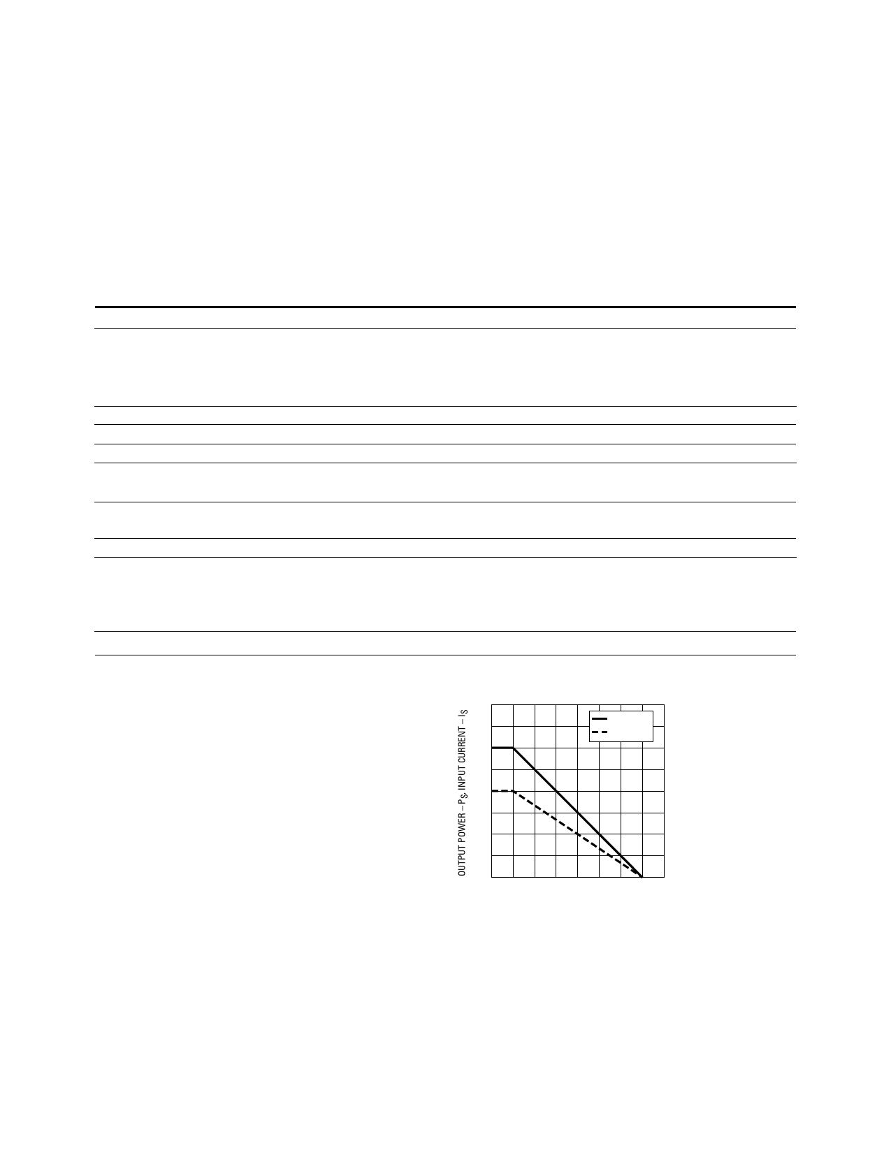
Case Temperature
Input Current[3]
Output Power[3]
Insulation Resistance at TS, VIO = 500 V
TS
175
IS, INPUT 400
PS, OUTPUT 600
RS
>109
Vpeak
Vpeak
Vpeak
Vpeak
°C
mA
mW
Ω
Notes:
1. Insulation characteristics are guaranteed only within the safety
maximum ratings which must be ensured by protective circuits
within the application. Surface Mount Classifications is Class A in
accordance with CECC00802.
2. Refer to the optocoupler section of the Isolation and Control
Components Designer’s Catalog, under Product Safety Regulations
section, (IEC/EN/DIN EN 60747-5-2) for a detailed description of
Method a and Method b partial discharge test profiles.
3. Refer to the following figure for dependence of PS and IS on ambient
temperature.
800
700
PS (mW)
IS (mA)
600
500
400
300
200
100
0
0 25 50 75 100 125 150 175 200
TS – CASE TEMPERATURE – °C
Share Link: 