HT48CA5 查看數據表(PDF) - Holtek Semiconductor
零件编号
产品描述 (功能)
生产厂家
HT48CA5 Datasheet PDF : 38 Pages
| |||
HT48RA5/HT48CA5
During the execution of an interrupt subroutine, other in-
terrupt acknowledge signals are held until the ²RETI² in-
struction is executed or the EMI bit and the related
interrupt control bit are set to 1 (if the stack is not full). To
return from the interrupt subroutine, ²RET² or ²RETI²
may be invoked. RETI will set the EMI bit to enable an in-
terrupt service, but RET will not.
Interrupts, occurring in the interval between the rising
edges of two consecutive T2 pulses, will be serviced on
the latter of the two T2 pulses, if the corresponding inter-
rupts are enabled. In the case of simultaneous requests
the following table shows the priority that is applied.
These can be masked by resetting the EMI bit.
Interrupt Source
Priority Vector
External Interrupt
1
04H
Timer/Event Counter 0 Overflow 2
08H
Timer/Event Counter 1 Overflow 3
0CH
The Timer/Event Counter 0/1 interrupt request flag
(T0F/T1F), external interrupt request flag (EIF), enable
Timer/Event Counter 0/1 interrupt bit (ET0I/ET1I), en-
able external interrupt bit (EEI) and enable master inter-
rupt bit (EMI) constitute an interrupt control register
(INTC) which is located at 0BH in the data memory. EMI,
EEI, ET0I and ET1I are used to control the enabling/dis-
abling of interrupts. These bits prevent the requested in-
terrupt from being serviced. Once the interrupt request
flags (T0F, T1F, EIF) are set, they will remain in the INTC
register until the interrupts are serviced or cleared by a
software instruction.
It is recommended that a program does not use the
²CALL subroutine² within the interrupt subroutine. In-
terrupts often occur in an unpredictable manner or
need to be serviced immediately in some applications.
If only one stack is left and enabling the interrupt is not
well controlled, the original control sequence will be dam-
aged once the ²CALL² operates in the interrupt subrou-
tine.
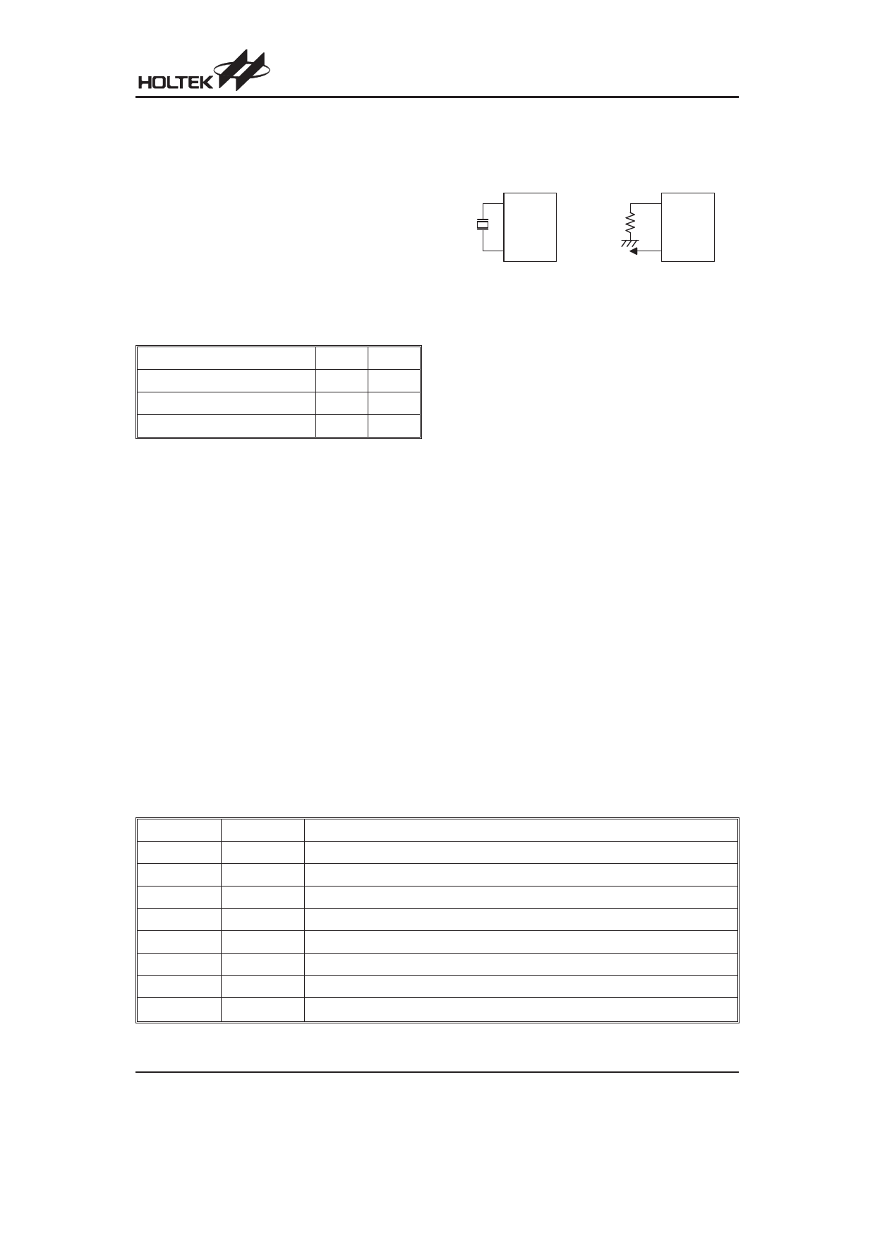
Oscillator Configuration
There are 2 oscillator circuits implemented in the
microcontroller.
O SC1
O SC1
O SC2
fS Y S /4
O SC2
N M O S O p e n D r a in
C r y s ta l O s c illa to r
R C O s c illa to r
System Oscillator
Both of them are designed for system clocks, namely
the RC oscillator and the crystal oscillator, which are de-
termined by options. No matter what oscillator type is
selected, the signal provides the system clock. The
HALT mode stops the system oscillator and resists the
external signal to conserve power.
If an RC oscillator is used, an external resistor between
OSC1 and VSS is required and the resistance should
range from 100kW to 820kW. The system clock, divided
by 4, is available on OSC2, which can be used to syn-
chronize external logic. The internal RC oscillator pro-
vides the most cost effective solution. However, the
frequency of oscillation may vary with VDD, tempera-
tures and the chip itself due to process variations. It is,
therefore, not suitable for timing sensitive operations
where an accurate oscillator frequency is desired.
If the crystal oscillator is used, a crystal across OSC1
and OSC2 is needed to provide the feedback and phase
shift required for the oscillator, and no other external
components are demanded. Instead of a crystal, the
resonator can also be connected between OSC1 and
OSC2 to get a frequency reference, but two external ca-
pacitors in OSC1 and OSC2 are required.
The WDT oscillator is a free running on-chip RC oscilla-
tor, and no external components are required. Even if
the system enters the power down mode, the system
clock is stopped, but the WDT oscillator still works with a
period of approximately 90ms. The WDT oscillator can
be disabled by ROM code option to conserve power.
Bit No.
0
1
2
3
4
5
6
7
Label
EMI
EEI
ET0I
ET1I
EIF
T0F
T1F
¾
Function
Controls the master (global) interrupt (1= enabled; 0= disabled)
Controls the external interrupt (1= enabled; 0= disabled)
Controls the Timer/Event Counter 0 interrupt (1= enabled; 0= disabled)
Controls the Timer/Event Counter 1 interrupt (1= enabled; 0= disabled)
External interrupt request flag (1= active; 0= inactive)
Internal Timer/Event Counter 0 request flag (1= active; 0= inactive)
Internal Timer/Event Counter 1 request flag (1= active; 0= inactive)
Unused bit, read as ²0²
INTC (0BH) Register
Rev. 1.40
10
May 22, 2009
Share Link: 