TDA3663 查看數據表(PDF) - Philips Electronics
零件编号
产品描述 (功能)
生产厂家
TDA3663 Datasheet PDF : 16 Pages
| |||
Philips Semiconductors
Very low dropout voltage/quiescent current
3.3 V voltage regulator
Preliminary specification
TDA3663
EXAMPLE 1
The regulator is stabilized with an electrolytic capacitor of
68 µF (ESR = 0.5 Ω). At Tamb = −40 °C, the capacitor
value is decreased to 22 µF and the ESR is increased
to 3.5 Ω. The regulator will remain stable at a temperature
of Tamb = −40 °C.
EXAMPLE 2
The regulator is stabilized with an electrolytic capacitor of
10 µF (ESR = 3.3 Ω). At Tamb = −40 °C, the capacitor
value is decreased to 3 µF and the ESR is increased to
20 Ω. The regulator will remain stable at a temperature of
Tamb = −40 °C.
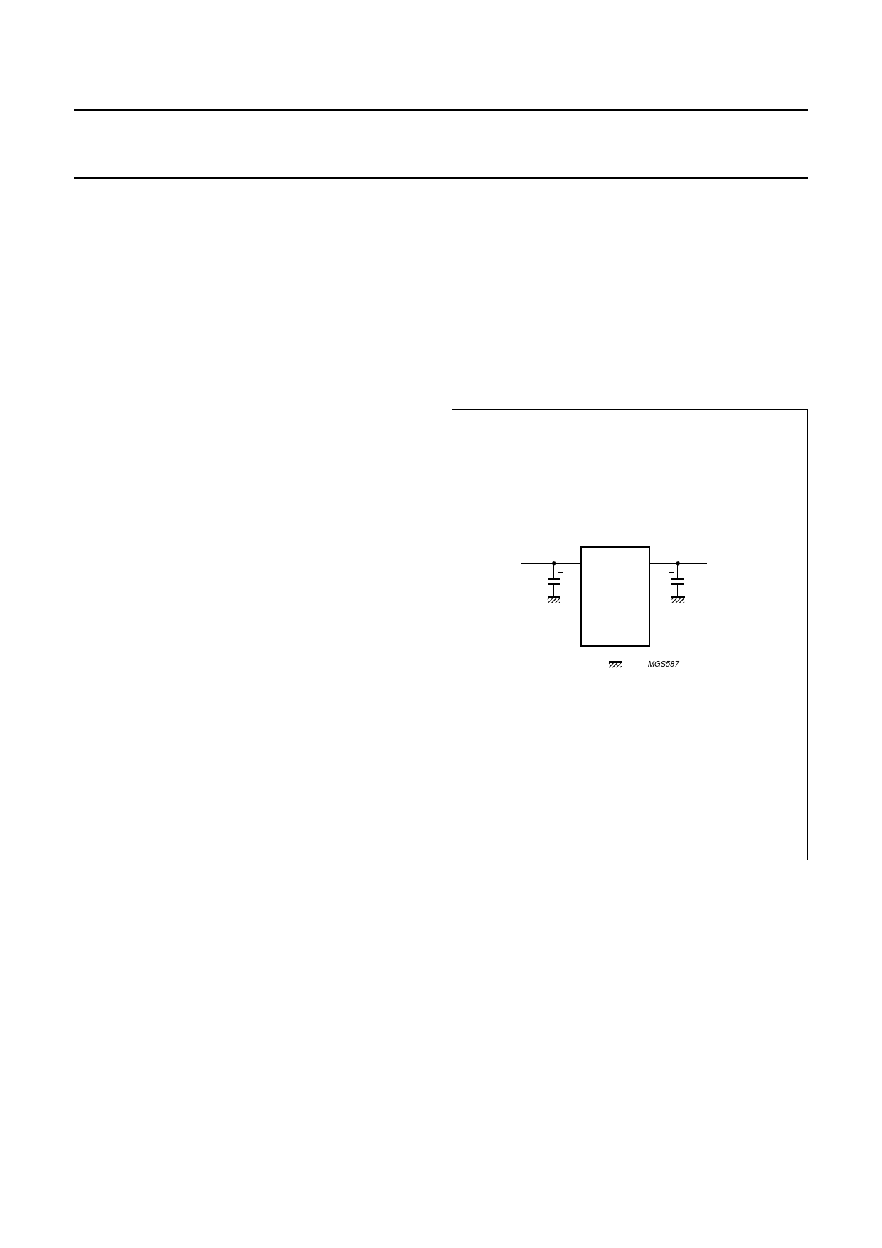
APPLICATION CIRCUIT WITH BACKUP FUNCTION
Sometimes a backup function is needed to supply, for
example, a microcontroller for a short period of time when
the supply voltage spikes to 0 V (or even −1 V).
This function can easily be built with the TDA3663 by using
an output capacitor with a large value. When the supply
voltage is 0 V (or −1 V), only a small current will flow into
pin REG from this output capacitor (a few µA).
The application circuit is given in Fig.7.
EXAMPLE 3
The regulator is stabilized with a 100 nF MKT capacitor
connected to the output. When the output current is over
200 µA full stability is guaranteed. Because the thermal
influence on the capacitor value is almost zero, the
regulator will remain stable at a temperature of
Tamb = −40 °C.
andbook, halfpage
VP C1(1)
1 µF
EXAMPLE 4
The regulator is stabilized with a 100 nF capacitor in
parallel with an electrolytic capacitor of 10 µF connected to
the output.
1
3
TDA3663
VREG = 3.3 V
C2 (2)
2, 4
MGS587
The regulator is now stable under all conditions and
independent of:
• The ESR of the electrolytic capacitor
• The value of the electrolytic capacitor
• The output current.
Application circuits
The maximum output current of the regulator equals:
(1) C1 is optional (to minimize supply noise only).
(2) C2 ≤ 4700 µF.
Fig.7 Application circuit with backup function
(SO4 version).
IREG(max) = -R----t-h---(-j----a-1-)--5-×---0--(--–-V----PT----a–--m---V-b---R----E---G----)
= -1---0---01----5-×--0---(--–V----T-P---a-–--m---3-b--.--3----) (mA)
When Tamb = 21 °C and VP = 14 V the maximum output
current equals 116 mA.
The total thermal resistance of the TDA3663 can be
decreased from 120 K/W to 50 K/W for the SO8 version.
For the SO4 version it can be decreased from
100 to 40 K/W when GND pins 2 and 4 of the package are
soldered to the printed-circuit board.
2000 Feb 01
8
Share Link: 