IDT54FCT388915T 查看數據表(PDF) - Integrated Device Technology
零件编号
产品描述 (功能)
生产厂家
IDT54FCT388915T Datasheet PDF : 11 Pages
| |||
IDT54/74FCT388915T 70/100/133/150
3.3V LOW SKEW PLL-BASED CMOS CLOCK DRIVER
MILITARY AND COMMERCIAL TEMPERATURE RANGES
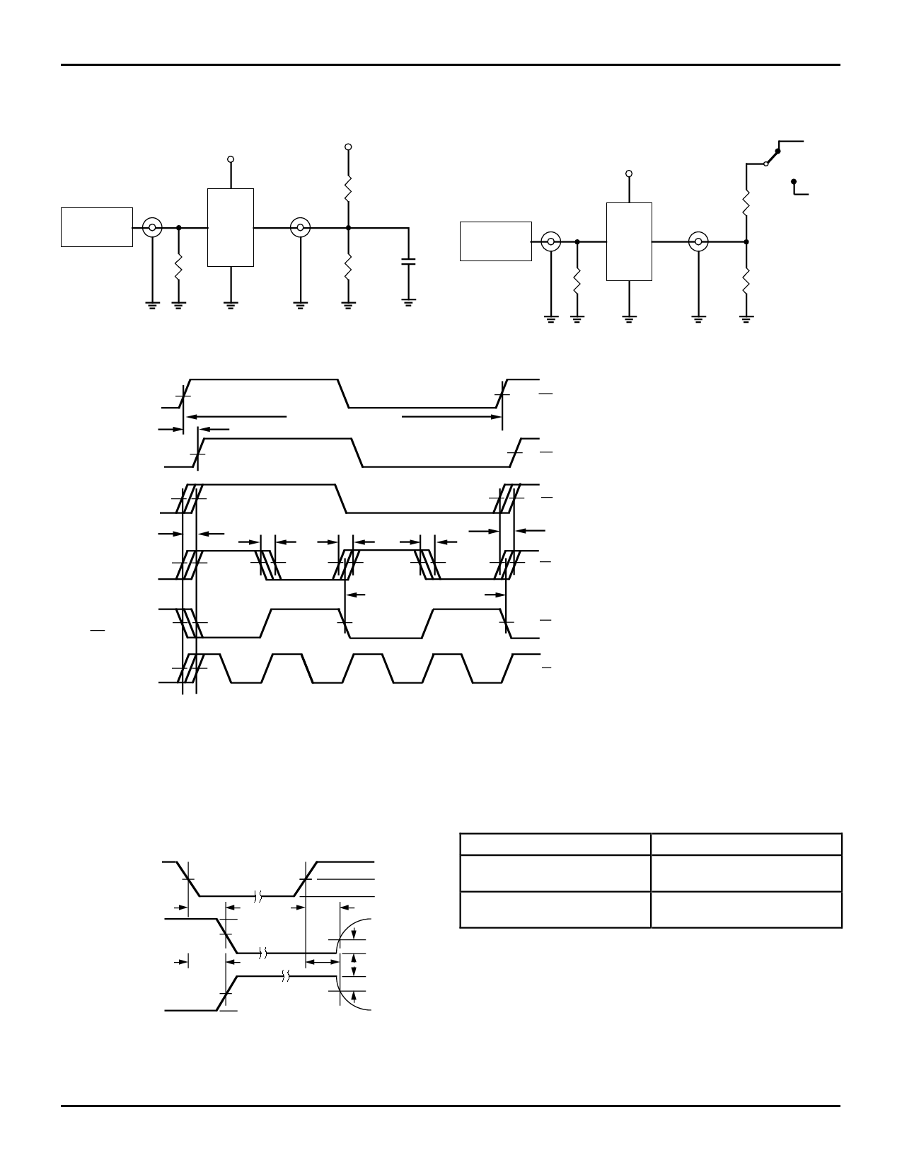
TEST CIRCUITS AND WAVEFORMS
50Ω TO VCC/2, CL = 20PF
VCC
VCC
ENABLE AND DISABLE TEST CIRCUIT
6.0V
VCC
VIN
Pulse
Generator
D.U.T.
RT
VOUT
100Ω
100Ω
20pF
CL
VIN
Pulse
Generator
D.U.T.
RT
VOUT
GND
500Ω
500Ω
3052 drw 05
3052 drw 06
PROPAGATION DELAY, OUTPUT SKEW
SYNC INPUT
(SYNC (1) or
SYNC (0))
FEEDBACK
INPUT
Q/2 OUTPUT
tSKEWALL
Q0-Q4
OUTPUTS
Q5 OUTPUT
tCYCLE SYNC INPUT
tPD
t SKEWf
t SKEWr
tSKEWf
tCYCLE "Q" OUTPUTS
1.5V
VCC/2
VCC/2
t SKEWr
VCC/2
1.5V
2Q OUTPUT
VCC/2
3052 drw 08
(These waveforms represent the configuration of Figure 3a)
NOTES:
1. The FCT388915T aligns rising edges of the FEEDBACK input and SYNC input, therefore the SYNC input does not require a 50% duty cycle.
2. All skew specs are measured between the VCC/2 crossing point of the appropriate output edges. All skews are specified as "windows", not as ± deviation
around a center point.
3. If a Q ouput is connected to the FEEDBACK input (this situation is not shown), the Q output frequency would match the SYNC input frequency, the 2Q
output would run at twice the SYNC frequency and the Q/2 output would run at half the SYNC frequency.
ENABLE AND DISABLE TIMES
SWITCH POSITION
ENABLE
DISABLE
3V
CONTROL
INPUT
tPZL
1.5V
0V
tPLZ
OUTPUT
NORMALLY
LOW
SWITCH
6V
tPZH
3V
1.5V
tPHZ
3V
0.3V VOL
OUTPUT
NORMALLY
HIGH
SWITCH
GND
NOTES:
1.5V
0V
0.3V VOH
0V
3052 drw 07
1. Diagram shown for input Control Enable-LOW and input Control
Disable-HIGH
2. Pulse Generator for All Pulses: tF ≤ 2.5ns; tR ≤ 2.5ns
Test
Switch
Disable Low
6V
Enable Low
Disable High
GND
Enable High
DEFINITIONS:
3052 tbl 10
CL= Load capacitance: includes jig and probe capacitance.
RT = Termination resistance: should be equal to ZOUT of the Pulse
Generator.
9.8
10
Share Link: 