IN1232 查看數據表(PDF) - Integral Corp.
零件编号
产品描述 (功能)
生产厂家
IN1232 Datasheet PDF : 6 Pages
| |||
IN1232
5. RST is an open drain output.
6. Must not exceed tTD minimum. See Table 1.
7. RST remains within 0.5V of VCC on power–down until VCC drops below 2.0V. RST remains
within 0.5V of GND on power–down until VCC drops below 2.0V.
8. Watchdog can not be disabled. It must be strobed to avoid resets.
OPERATION – POWER MONITOR
The IN1232 detects out–of–tolerance power supply conditions and warns a processor–based system
of impending power failure. When VCC falls below a preset level as defined by TOL (Pin 3), the VCC
comparator outputs the signals RST (Pin 5) and RST (Pin 6). When TOL is connected to ground, the
RST and RST signals become active as VCC falls below 4.75 volts. When TOL is connected to VCC, the
RST and RST signals become active as VCC falls below 4.5 volts. The RST and RST are excellent
control signals for a microprocessor, as processing is stopped at the last possible moments of
valid VCC. On power–up, RST and RST are kept active for a minimum of 250 ms to allow the power
supply and processor to stabilize.
OPERATION – PUSHBUTTON RESET
The IN1232 provides an input pin for direct connection to a pushbutton (Figure 2). The pushbutton
reset input requires an active low signal. Internally, this input is de-bounced and timed such that RST
and RST signals of at least 250 ms minimum are generated. The 250 ms delay starts as the
pushbutton reset input is released from low level.
OPERATION – WATCHDOG TIMER
A watchdog timer function forces RST and RST signals to the active state when the ST input is not
stimulated for a predetermined time period. The time period is set by the TD input to be typically 150
ms with TD connected to ground, 600 ms with TD left unconnected, and 1.2 sec-
onds with TD connected to VCC. The watchdog timer starts timing out from the set time period as soon
as RST and RST are inactive. If a high–to–low transition occurs on the ST input pin prior to time–out,
the watchdog timer is reset and begins to time–out again. If the watchdog timer is allowed to time-out,
then the RST and RST signals are driven to the active state for 250 ms minimum. The ST input can be
derived from microprocessor address signals, data signals, and/or control signals. When the
microprocessor is functioning normally, these signals would, as a matter of routine, cause the watch-
dog to be reset prior to time–out. To guarantee that the watchdog timer does not time–out, a high–to–
low transition must occur at or less than the minimum shown in Table 1. A typical circuit example is
shown in Figure 3.
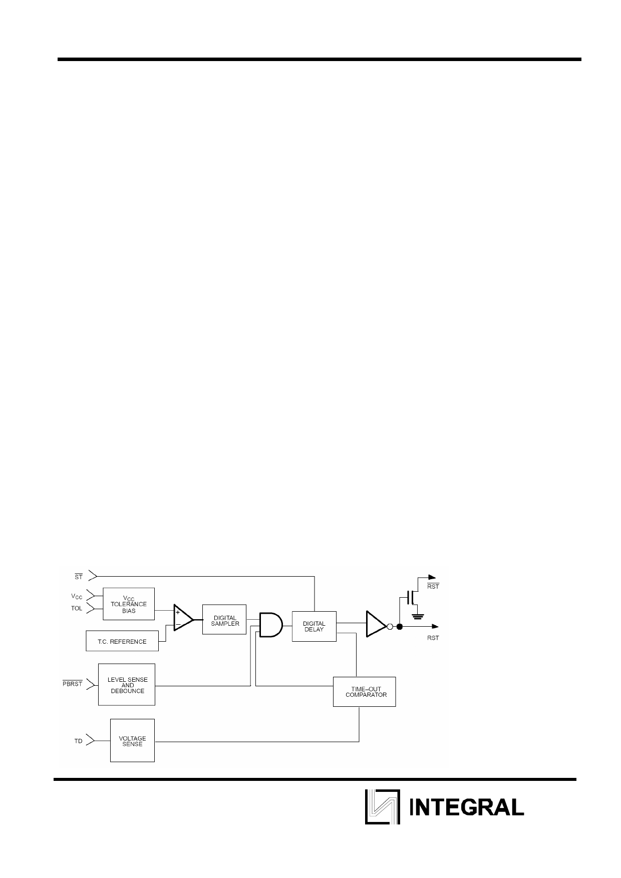
MICROMONITOR BLOCK DIAGRAM
3
Share Link: 