TDA8565Q жҹҘзңӢж•ёж“ҡиЎЁпјҲPDFпјү - Philips Electronics
йӣ¶д»¶зј–еҸ·
дә§е“ҒжҸҸиҝ° (еҠҹиғҪ)
з”ҹдә§еҺӮ家
TDA8565Q
Philips Electronics

TDA8565Q Datasheet PDF : 14 Pages
| |||
Philips Semiconductors
4 Г— 12 W single-ended car radio
power ampliп¬Ғer with diagnostic interface
Product speciп¬Ғcation
TDA8565Q
DC CHARACTERISTICS
VP = 14.4 V; Tamb = 25 В°C; measured in Fig.14; unless otherwise speciп¬Ғed.
SYMBOL
PARAMETER
CONDITIONS
MIN. TYP. MAX. UNIT
Supply
VP
supply voltage
Iq
quiescent current
VO
DC output voltage
Mute select switch
V14
switch-on voltage level
MUTE CONDITION
Vmute
VO
mute voltage
output signal in mute position
STANDBY CONDITION
Vsb
DC voltage in standby condition
Isb
DC current in standby condition
Vsw
switch-on current
Diagnostic output (pin 16)
VDIAG
diagnostic output voltage
note 1
note 2
VI(max) = 1 V; f = 1 kHz
any short-circuit or clipping
6.0 14.4 18.0 V
вҲ’
88 160 mA
вҲ’
6.95 вҲ’
V
8.5 вҲ’
вҲ’
V
3.3 вҲ’
вҲ’
вҲ’
6.4 V
2
mV
0
вҲ’
2
V
вҲ’
вҲ’
100 ВөA
вҲ’
12 40 ВөA
вҲ’
вҲ’
0.6 V
Notes
1. The circuit is DC adjusted at VP = 6 to 18 V and AC operating at VP = 8.5 to 18 V.
2. At 18 V < VP < 30 V the DC output voltage вүӨ1вҒ„2VP.
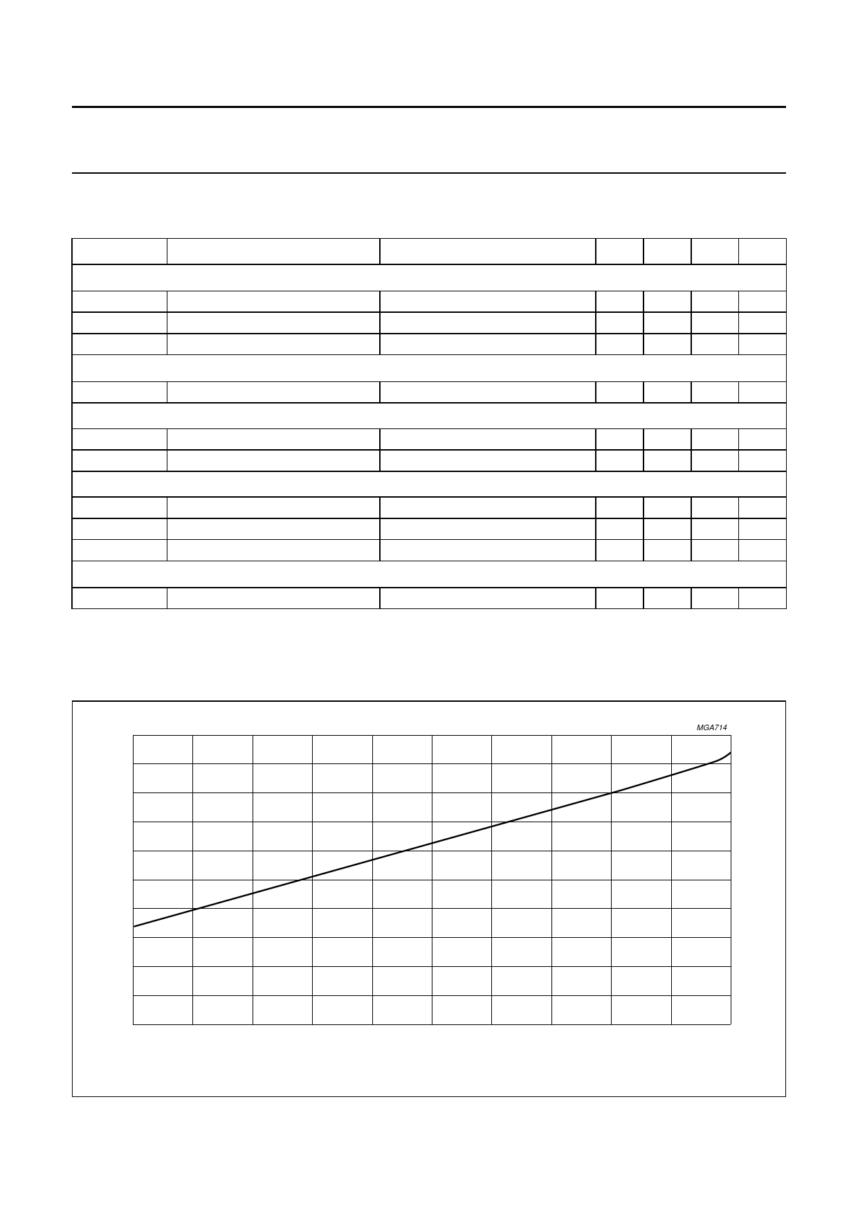
100
handbook, full pagewidth
Iq
(mA)
92
MGA714
84
76
68
60
8
1995 Dec 08
10
12
14
16
VP (V)
18
Fig.7 Quiescent current as a function of supply voltage.
7
Share Link: