IS93C46A 查看數據表(PDF) - Integrated Silicon Solution
零件编号
产品描述 (功能)
生产厂家
IS93C46A Datasheet PDF : 13 Pages
| |||
ISSI ®
IS93C46A IS93C56A IS93C66A
1,024/2,048/4,096-BIT SERIAL ELECTRICALLY
ERASABLE PROM
NOVEMBER 2002
FEATURES
• Industry-standard Microwire Interface
— Non-volatile data storage
— Low voltage operation:
Vcc = 2.5V to 5.5V
— Full TTL compatible inputs and outputs
— Auto increment for efficient data dump
• User Configured Memory Organization
— By 16-bit or by 8-bit
• Hardware and software write protection
— Defaults to write-disabled state at power-up
— Software instructions for write-enable/disable
• Enhanced low voltage CMOS E2PROM
technology
• Versatile, easy-to-use Interface
— Self-timed programming cycle
— Automatic erase-before-write
— Programming status indicator
— Word and chip erasable
— Stop SK anytime for power savings
• Durable and reliable
— 40-year data retention after 1M write cycles
— 1 million write cycles
— Unlimited read cycles
— Schmitt-trigger inputs
• Industrial and Automotive Temperature Grade
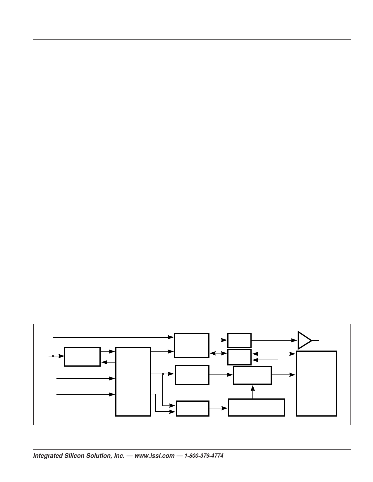
FUNCTIONAL BLOCK DIAGRAM
DESCRIPTION
The IS93C46A/56A/66A is a low-cost 1kb/2kb/
4kb non-volatile, ISSI ® serial EEPROM. It is
fabricated using an enhanced CMOS design and
process. The IS93C46A/56A/66A contain power-
efficient read/write memory, and organziation of
either 128/256/512 bytes of 8 bits or 64/128/256
words of 16 bits. When the ORG pin is
connected to Vcc or left unconnected, x16 is
selected; when it is connected to ground, x8 is
selected. The IS93C46A/56A/66A is fully
backwards compatible with IS93C46/56/66.
An instruction set controls the operation of the
devices, including read, write, and mode-enable
functions. The data out pin (Dout) indicates the
status of the device during the self-timed non-
volatile programming cycle. The self-timed write
cycle includes an automatic erase-before-write
capability. To protect against inadvertent writes,
the WRITE instruction is accepted only while the
chip is in the write-enabled state. Data is written
once per WRITE instruction to the x8 byte or x16
word selected. If Chip Select (CS) is brought
HIGH just after initiation of the write cycle, the
Dout pin would indicate the Ready/Busy status of
the write activity.
DIN
INSTRUCTION
REGISTER
CS
SK
INSTRUCTION
DECODE,
CONTROL,
AND
CLOCK
GENERATION
DATA
REGISTER
ADDRESS
REGISTER
WRITE
ENABLE
DUMMY
BIT
R/W
AMPS
ADDRESS
DECODER
HIGH VOLTAGE
GENERATOR
DOUT
EEPROM
ARRAY
128/256/512x16
64/128/256/x8
Copyright © 2002 Integrated Silicon Solution, Inc. All rights reserved. ISSI reserves the right to make changes to this specification and its products at any time
without notice. ISSI assumes no liability arising out of the application or use of any information, products or services described herein. Customers are advised to
obtain the latest version of this device specification before relying on any published information and before placing orders for products.
Integrated Silicon Solution, Inc. — www.issi.com — 1-800-379-4774
1
Rev. A
11/12/02
Share Link: 