74F2952 查看數據表(PDF) - Philips Electronics
零件编号
产品描述 (功能)
生产厂家
74F2952 Datasheet PDF : 14 Pages
| |||
Philips Semiconductors
Transceivers
Product specification
74F2952, 74F2953
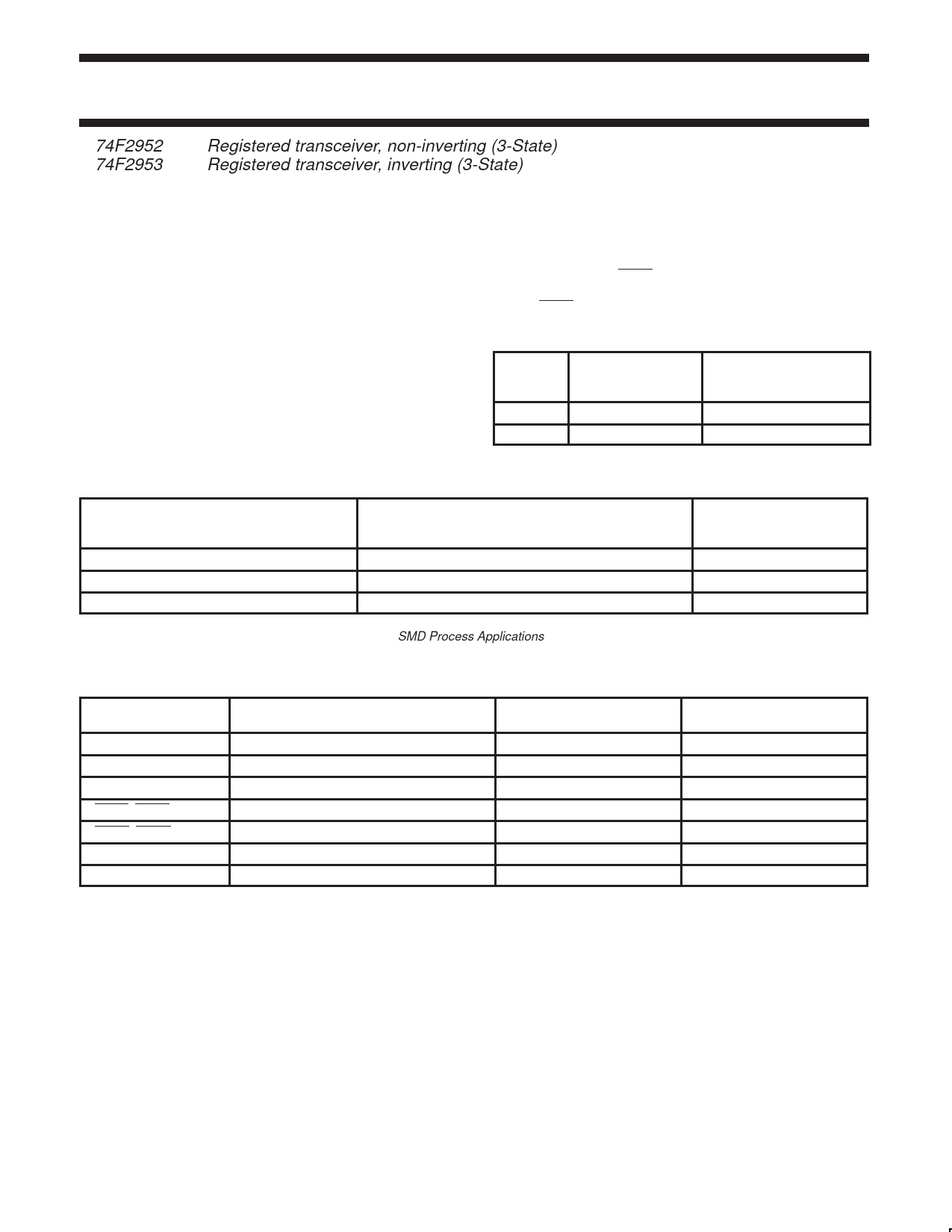
74F2952
74F2953
Registered transceiver, non-inverting (3-State)
Registered transceiver, inverting (3-State)
FEATURES
• 8-bit registered transceivers
• Two 8-bit, back-to-back registers store data moving in both
directions between two bidirectional buses
• Separate Clock, Clock Enable and 3-State Enable provided for
each register
• 74F2952 non-inverting
• 74F2953 inverting
• AM2952/2953 functional equivalent
• ‘A’ outputs sink 24mA and source 3mA
• ‘B’ outputs sink 64mA and source 15mA
• 300 mil wide 24-pin Slim DIP package
DESCRIPTION
The 74F2952 and 74F2953 are 8-bit registered transceivers. Two
8-bit back-to-back registers store data flowing in both directions
between two bi-directional buses. Data applied to the inputs is
entered and stored on the rising edge of the Clock (CPXX) provided
that the Clock Enable (CEXX) is Low. The data is then present at
the 3-State output buffers, but is only accessible when the Output
Enable (OEXX) is Low. Data flow from ‘A’ inputs to ‘B’ outputs is the
same as for ‘B’ inputs to ‘A’ outputs.
TYPE
74F2952
74F2953
TYPICAL fMAX
160MHz
160MHz
TYPICAL
SUPPLY CURRENT
(TOTAL)
105mA
105mA
ORDERING INFORMATION
DESCRIPTION
24-pin Plastic Slim DIP (300mil)
24-pin Plastic SOL1
COMMERCIAL RANGE
VCC = 5V ±10%,
Tamb = 0°C to +70°C
N74F2952N, N74F2953N
N74F2952D, N74F2953D
PACKAGE
DRAWING
NUMBER
SOT222-1
SOT137-1
28-pin Plastic Leaded Chip Carrier
N74F2952A, N74F2953A
SOT261-2
NOTE:
1. Thermal mounting techniques are recommended. See SMD Process Applications for a discussion of thermal consideration for surface
mounted devices.
INPUT AND OUTPUT LOADING AND FAN-OUT TABLE
PINS
DESCRIPTION
74F(U.L.)
HIGH/LOW
A0 – A7
Port A, 3-State inputs
3.5/1.0
B0 – B7
Port B, 3-State inputs
3.5/1.0
CPAB, CPBA
Clock inputs
1.0/1.0
CEAB, CEBA
Clock Enable inputs
1.0/1.0
OEAB, OEBA
Output Enable inputs
1.0/1.0
A0 – A7
Port A, 3-State outputs
150/40
B0 – B7
Port B, 3-State outputs
750/106.7
NOTE: One (1.0) FAST unit load is defined as: 20µA in the High state and 0.6mA in the Low state.
LOAD VALUE
HIGH/LOW
70µA/0.6mA
70µA/0.6mA
20µA/0.6mA
20µA/0.6mA
20µA/0.6mA
3.0mA/24mA
15mA/64mA
1989 Sep 22
2
853–1097 97708
Share Link: 