L5983 查看數據表(PDF) - STMicroelectronics
零件编号
产品描述 (功能)
生产厂家
L5983 Datasheet PDF : 37 Pages
| |||
Functional description
L5983
4.1
Oscillator and synchronization
Figure 4 shows the block diagram of the oscillator circuit. The internal oscillator provides a
constant frequency clock. Its frequency depends on the resistor externally connect to FSW
pin. In case the FSW pin is left floating the frequency is 250kHz; it can be increased as
shown in Figure 6 by external resistor connected to ground.
To improve the line transient performance and to keep the PWM gain constant versus the
input voltage, the voltage feed forward is implemented by changing the slope of the
sawtooth according to the input voltage change (see Figure 5.a).
The slope of the sawtooth also changes if the oscillator frequency is increased by the
external resistor. In this way a frequency feed forward is implemented (Figure 5.b) in order to
keep the PWM gain constant versus the switching frequency (see Section 5.4 for PWM gain
expression).
On the SYNCH pin the synchronization signal is generated. This signal has a phase shift of
180° with respect to the clock. This delay is useful when two devices are synchronized
connecting the SYNCH pin together. When SYNCH pins are connected, the device with
higher oscillator frequency works as Master, so the Slave device switches at the frequency
of the Master but with a delay of half a period. This minimizes the RMS current flowing
through the input capacitor [see L5988D Data sheet].
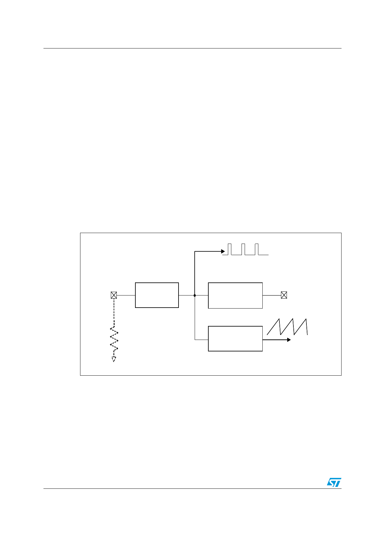
Figure 4. Oscillator circuit block diagram
FSW
Clock
Generator
Clock
Synchronization
SYNCH
Ramp
Generator
Sawtooth
The device can be synchronized to work at higher frequency feeding an external clock
signal. The synchronization changes the sawtooth amplitude, changing the PWM gain
(Figure 5.c). This changing has to be taken into account when the loop stability is studied.
To minimize the change of the PWM gain, the free running frequency should be set (with a
resistor on FSW pin) only slightly lower than the external clock frequency. This pre-adjusting
of the frequency will change the sawtooth slope in order to get negligible the truncation of
sawtooth, due to the external synchronization.
9/37
Share Link: 