LC723462 查看數據表(PDF) - SANYO -> Panasonic
零件编号
产品描述 (功能)
生产厂家
LC723462 Datasheet PDF : 13 Pages
| |||
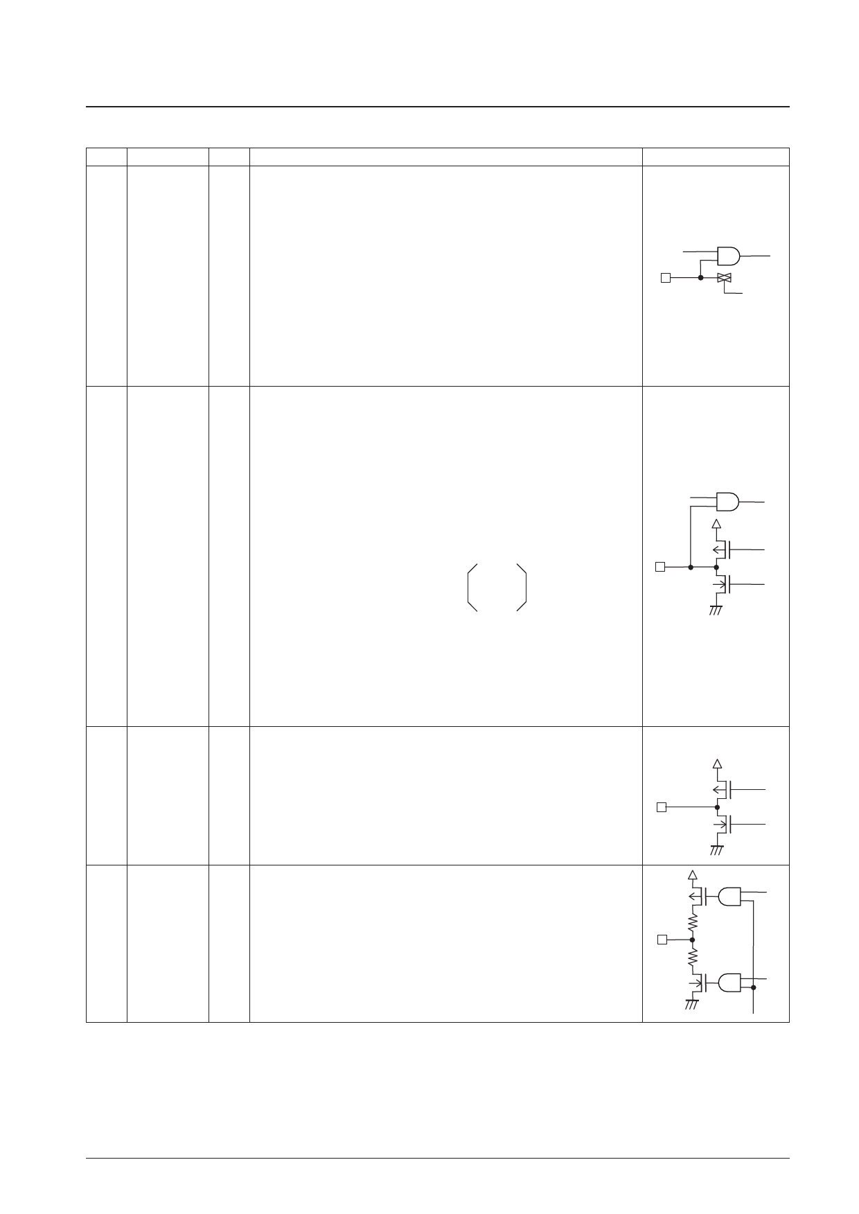
LC723461W, 723462W
Continued from preceding page.
Pin No.
Pin
22
PF0/ADI0
21
PF1/ADI1
20
PF2/ADI3
I/O
Function
General-purpose input and A/D converter input shared function ports. The IOS
instruction is used to switch between the general-purpose input and A/D converter
port functions. The general-purpose input and A/D converter port functions can be
switched in a units, with 0 specifying general-purpose input, and 1 specifying the A/D
converter input function. To select the A/D converter function, set up the A/D
converter pin with an IOS instruction with Pwn set to 1. The A/D converter is started
with the UCC instruction (b3 = 1, b2 = 1). The ADCE flag is set when the conversion
I completes. The INR instruction is used to read in the data.
*: If an input instruction is executed for one of these pins which is set up for analog
input, the read in data will be at the low level since CMOS input is disabled. In
backup mode these pins go to the input disabled high-impedance state. These
ports are set to their general-purpose input port function after a reset. The A/D
converter is a 8-bit successive approximation type converter, and features a
conversion time of 0.64 ms. Note that the full-scale A/D converter voltage (FFH) is
VDC3/2.0 V.
I/O circuit
CMOS input/analog input
LCD driver segment output and general-purpose I/O shared function ports.
The IOS instruction is used for switching between the segment output and general-
purpose I/O functions and between input and output for the general-purpose I/O port
function.
• When used as segment output ports
31
PG3/S20
32
PG2/S19
The segment output port is selected with the IOS instruction (Pwn = 8).
b0 to b3 = S17 to 20/PG0 to 3 (0: Segment output, 1: PG0 to 3)
The segment output port is selected with the IOS instruction (Pwn = 9).
33
PG1/S18
b0 to b3 = S13 to 16/PH0 to 3 (0: Segment output, 1: PH0 to 3)
34
PG0/S17
• When used as general-purpose I/O ports
The IOS instruction is used to select input or output. Note that the mode can be
O
set in a bit units.
35
PH3/S16
b0 = PG0
b0 = PH0
36
PH2/S15
b1 = PG1
b1 = PH1
0: Input
37
PH1/S14
38
PH0/S13
*2
b2 = PG2
b3 = PG3
b2 = PH2
b3 = PH3
1: Output
Note that there is a mask option that allows these pins to be used as n-channel open
drain ports.
In backup mode, these pins go to the input disabled high-impedance state if set up as
general-purpose outputs, and are fixed at the low level if set up as segment outputs.
These ports are set up as segment outputs after a reset.
Although the general-purpose port/LCD port setting is a mask option, the IOS
instruction must be used as described above to set up the port function.
39 to
50
S12 to S1
LCD driver segment output pins.
A 1/4-duty 1/2-bias drive technique is used.
O The frame frequency is 75 Hz.
In backup mode, these outputs are fixed at the low level.
After a reset, these outputs are fixed at the low level.
CMOS push-pull
CMOS push-pull
LCD driver common output pins.
51
COM4
A 1/4-duty 1/2-bias drive technique is used.
52
COM3
O The frame frequency is 75 Hz.
53
COM2
In backup mode, these outputs are fixed at the low level.
54
COM1
After a reset, these outputs are fixed at the low level.
Continued on next page.
No. 7275-8/13
Share Link: 