LCMXO2-4000ZE-3MG132I 查看數據表(PDF) - Lattice Semiconductor
零件编号
产品描述 (功能)
生产厂家
LCMXO2-4000ZE-3MG132I Datasheet PDF : 106 Pages
| |||
Architecture
MachXO2 Family Data Sheet
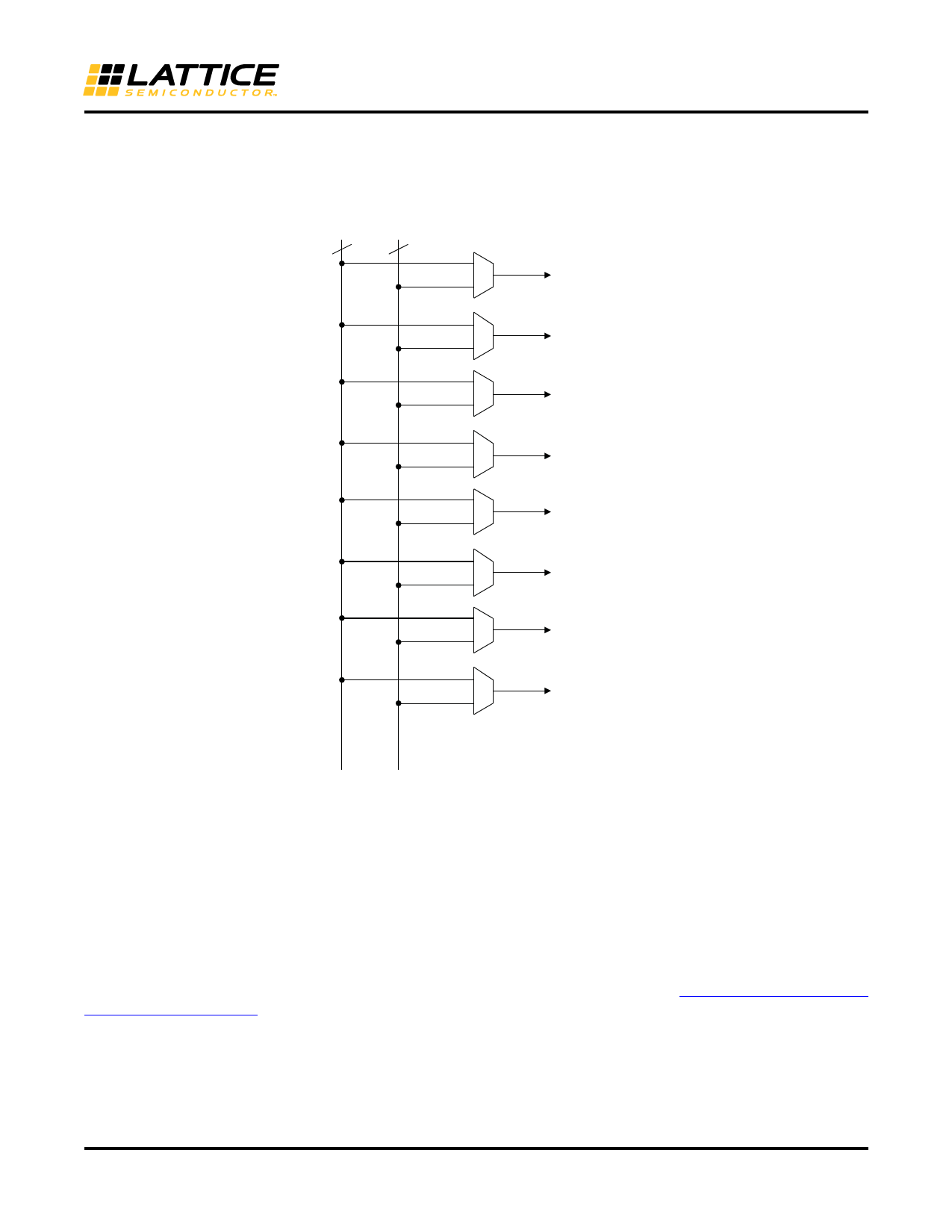
Eight secondary high fanout nets are generated from eight 8:1 muxes as shown in Figure 2-6. One of the eight
inputs to the secondary high fanout net input mux comes from dual function clock pins and the remaining seven
come from internal routing. The maximum frequency for the secondary clock network is shown in MachXO2 Exter-
nal Switching Characteristics table.
Figure 2-6. Secondary High Fanout Nets for MachXO2 Devices
1
7
8:1
Secondary High
Fanout Net 0
Secondary High
8:1
Fanout Net 1
Secondary High
8:1
Fanout Net 2
Secondary High
8:1
Fanout Net 3
Secondary High
8:1
Fanout Net 4
Secondary High
8:1
Fanout Net 5
Secondary High
8:1
Fanout Net 6
Secondary High
8:1
Fanout Net 7
Clock Pads Routing
sysCLOCK Phase Locked Loops (PLLs)
The sysCLOCK PLLs provide the ability to synthesize clock frequencies. The MachXO2-640U, MachXO2-1200/U
and larger devices have one or more sysCLOCK PLL. CLKI is the reference frequency input to the PLL and its
source can come from an external I/O pin or from internal routing. CLKFB is the feedback signal to the PLL which
can come from internal routing or an external I/O pin. The feedback divider is used to multiply the reference fre-
quency and thus synthesize a higher frequency clock output.
The MachXO2 sysCLOCK PLLs support high resolution (16-bit) fractional-N synthesis. Fractional-N frequency syn-
thesis allows the user to generate an output clock which is a non-integer multiple of the input frequency. For more
information about using the PLL with Fractional-N synthesis, please see TN1199, MachXO2 sysCLOCK PLL
Design and Usage Guide.
Each output has its own output divider, thus allowing the PLL to generate different frequencies for each output. The
output dividers can have a value from 1 to 128. The CLKOS2 and CLKOS3 dividers may also be cascaded together
to generate low frequency clocks. The CLKOP, CLKOS, CLKOS2, and CLKOS3 outputs can all be used to drive the
MachXO2 clock distribution network directly or general purpose routing resources can be used.
2-7
Share Link: 