LF503RW 查看數據表(PDF) - MicroPower Direct, LLC
零件编号
产品描述 (功能)
生产厂家
LF503RW Datasheet PDF : 2 Pages
| |||
Model Selection Guide
www.micropowerdirect.com
Model
Number
Input
Voltage (VDC)
Current (mA)
Voltage
Nominal Range
Full-Load No-Load (VDC)
Output
Current
(mA, Max)
Current
(mA, Min)
Reflected
Ripple Cur.
(mA)
Efficiency
(%, Typ)
Fuse Rating
Slow-Blow
(mA)
LF501RW
LF502RW
LF503RW
LF504RW
LF505RW
LF506RW
LF507RW
LF511RW
LF512RW
LF513RW
LF514RW
LF515RW
LF516RW
LF517RW
LF521RW
LF522RW
LF523RW
LF524RW
LF525RW
LF526RW
LF527RW
12
9.0 - 18.0
434
12
9.0 - 18.0
521
12
9.0 - 18.0
502
12
9.0 - 18.0
502
12
9.0 - 18.0
521
12
9.0 - 18.0
501
12
9.0 - 18.0
503
24 18.0 - 36.0
212
24 18.0 - 36.0
254
24 18.0 - 36.0
245
24 18.0 - 36.0
245
24 18.0 - 36.0
254
24 18.0 - 36.0
245
24 18.0 - 36.0
246
48 36.0 - 75.0
106
48 36.0 - 75.0
127
48 36.0 - 75.0
123
48 36.0 - 75.0
122
48 36.0 - 75.0
127
48 36.0 - 75.0
122
48 36.0 - 75.0
123
20
3.3
1,200
120.0
25
76
1,500
20
5.0
1,000
100.0
25
80
1,500
20
12.0
417
41.7
25
83
1,500
20
15.0
333
33.3
25
83
1,500
20
±5.0
±500
±50.0
25
80
1,500
20 ±12.0
±208
±20.8
25
83
1,500
20 ±15.0
±167
±16.7
25
83
1,500
5
3.3
1,200
120.0
15
78
700
5
5.0
1,000
100.0
15
82
700
5
12.0
417
41.7
15
85
700
5
15.0
333
33.3
15
85
700
5
±5.0
±500
±50.0
15
82
700
5
±12.0
±208
±20.8
15
85
700
5
±15.0
±167
±16.7
15
85
700
3
3.3
1,200
120.0
10
78
350
3
5.0
1,000
100.0
10
82
350
3
12.0
417
41.7
10
85
350
3
15.0
333
33.3
10
85
350
3
±5.0
±500
±50.0
10
82
350
3
±12.0
±208
±20.8
10
85
350
3
±15.0
±167
±16.7
10
85
350
Notes:
1. When measuring output ripple, it is recommended that an external 0.47 µF ceramic capacitor be placed from the +Vout
pin to the -Vout pin for single output units and from each output to common for dual output units. For noise sensitive
applications, the use of 3.3 µF capacitors will reduce the output ripple.
2. Transient recovery is measured to within a 1% error band for a load step change of 75% to 100%.
3. No-load operation will not damage these units, however, they may not meet specifications.
4. Dual output units may provide a 10V, 24V or 30V output. To do this, connect the load across the positive (+Vout) and
negative (-Vout) outputs and float the output common.
5. The converter should be connected to a low ac-impedance source. An input source with a highly inductive impedance
may affect the stability of the converter. In applications where the converter output loading is high and input power is
supplied over long lines, it may be necessary to use a capacitor on the input to insure start-up. In this case, it is recom-
mended that a low ESR (ESR <1.0 at 100 kHz) capacitor be mounted close to the converter. For 12V input units a 4.7
µF is recommended, and for 24V & 48V units a 2.2 µF.
6. It is recommended that a fuse be used on the input of a power supply for protection. See the table above for the correct
rating.
Remote ON/OFF
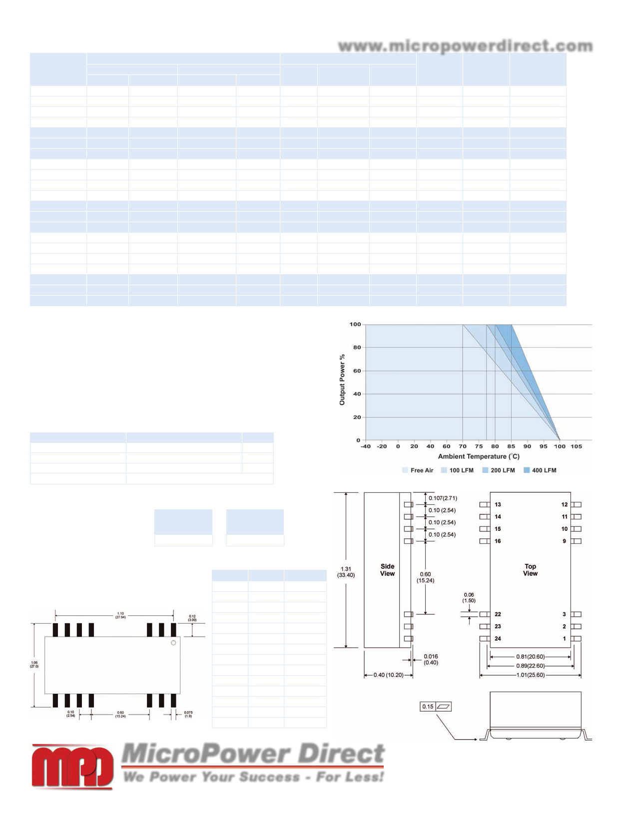
Derating Curve
Parameter
Supply On
Supply Off
Standby Input Current
Control Common
Remote ON/OFF Notes:
1. Maximum sink current at the
on/off pin (pin 1) during a logic
low is 300 µA.
2. Maximum allowable leakage
current of a switch connected
to the on/off terminal (Pin 1)
at logic high (2.5V to 100V)
is 200 µA.
Condition
Units
2.5 to 5.5 or Open Circuit VDC
-0.7 to 0.8
VDC
10
mA
Referenced to Negative Input (-Vin)
Capacitive Load
Single
Output (Max)
Dual
Output (Max)
680 µF
100 µF
Pin Connections
Mechanical Dimensions
Pin Single Dual
Board Layout
1 On/Off On/Off
2
-Vin
-Vin
3
-Vin
-Vin
9
NC Common
10
NC
NC
11
NC
-Vout
12
NC
NC
13
NC
NC
14 +Vout +Vout
15
NC
NC
16 -Vout Common
22
+Vin
+Vin
23
+Vin
+Vin
24
NC
NC
NC: No Connection
MicroPower Direct
We Power Your Success - For Less!
Notes:
• All dimensions are typical in inches (mm)
• Tolerance x.xx = ±0.01 (±0.25)
• Pin 1 is marked by a “dot” or indentation on the unit
292 Page Street Ste D Stoughton, MA 02072 • TEL: (781) 344-8226 • FAX: (781) 344-8481 • E-Mail: sales@micropowerdirect.com
Share Link: 