LH7A400 查看數據表(PDF) - Sharp Electronics
零件编号
产品描述 (功能)
生产厂家
LH7A400 Datasheet PDF : 53 Pages
| |||
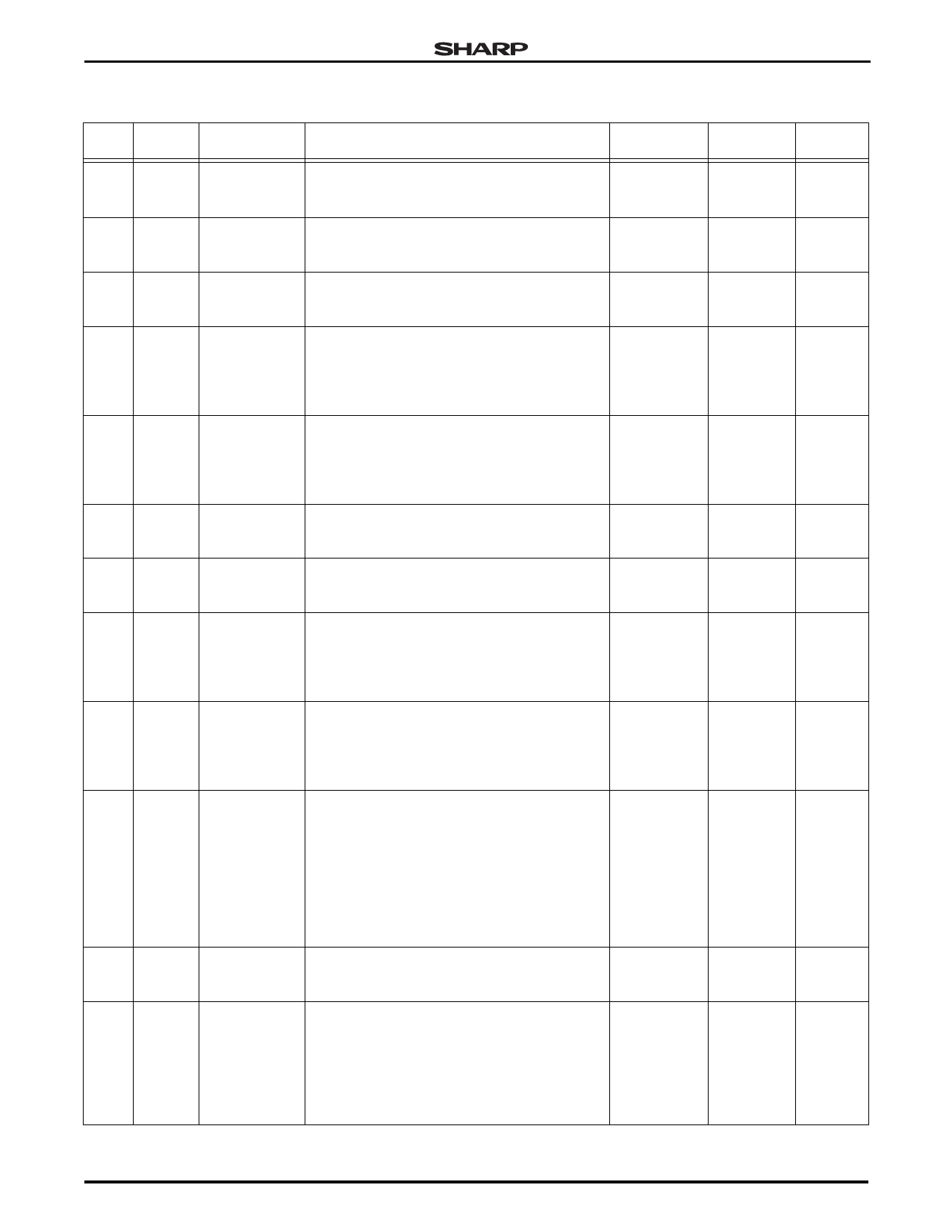
32-Bit System-on-Chip
LH7A400
Table 1. Functional Pin List (Cont’d)
PBGA CABGA
PIN PIN
SIGNAL
L6
P4 PG2/nPCIOR
M6
R3 PG3/nPCIOW
N6
T2 PG4/nPCREG
M7
P5 PG5/nPCCE1
M8
R4 PG6/nPCCE2
N4
T3 PG7/PCDIR
P4
P6
PH0/
PCRESET1
R4
T4
PH1/CFA8/
PCRESET2
T4
M7
PH2/
nPCSLOTE1
PH3/CFA9/
N7
T5 PCMCIAA25/
nPCSLOTE2
P8
R6
PH4/
nPCWAIT1
PH5/CFA10/
P5
R7 PCMCIAA24/
nPCWAIT2
DESCRIPTION
RESET
STATE
• GPIO Port G
• I/O Read Strobe for PC Card (PCMCIA or
CompactFlash) in single or dual card mode
LOW: PG2
• GPIO Port G
• I/O Write Strobe for PC Card (PCMCIA or
CompactFlash) in single or dual card mode
LOW: PG3
• GPIO Port G
• Register Memory Access for PC Card (PCMCIA LOW: PG4
or CompactFlash) in single or dual card mode
• GPIO Port G
• Card Enable 1 for PC Card (PCMCIA or
CompactFlash) in single or dual card mode. LOW: PG5
This signal and nPCCE2 are used by the PC
Card for decoding low and high byte accesses.
• GPIO Port G
• Card Enable 2 for PC Card (PCMCIA or
CompactFlash) in single or dual card mode. LOW: PG6
This signal and nPCCE1 are used by the PC
Card for decoding low and high byte accesses.
• GPIO Port G
• Direction for PC Card (PCMCIA or
CompactFlash) in single or dual card mode
LOW: PG7
• GPIO Port H
• Reset Card 1 for PC Card (PCMCIA or
CompactFlash) in single or dual card mode
Input: PH0
• GPIO Port H
• Address Bit 8 for PC Card (CompactFlash) in
single card mode
• Reset Card 2 for PC Card (PCMCIA or
CompactFlash) in dual card mode
Input: PH1
• GPIO Port H
• Enable Card 1 for PC Card (PCMCIA or
CompactFlash) in single or dual card mode. Input: PH2
This signal is used for gating other control sig-
nals to the appropriate PC Card.
• GPIO Port H
• Address Bit 9 for PC Card (CompactFlash) in
single card mode
• Address Bit 25 for PC Card (PCMCIA) in single
card mode
Input: PH3
• Enable Card 2 for PC Card (PCMCIA or
CompactFlash) in dual card mode. This signal
is used for gating other control signals to the
appropriate PC Card.
• GPIO Port H
• WAIT Signal for Card 1 for PC Card (PCMCIA Input: PH4
or CompactFlash) in single or dual card mode
• GPIO Port H
• Address Bit 10 for PC Card (CompactFlash) in
single card mode
• Address Bit 24 for PC Card (PCMCIA) in single Input: PH5
card mode
• WAIT Signal for Card 2 for PC Card (PCMCIA
or CompactFlash) in dual card mode
STANDBY OUTPUT
STATE
DRIVE
No Change 8 mA
No Change 8 mA
No Change 8 mA
No Change 8 mA
No Change 8 mA
No Change 8 mA
No Change 8 mA
No Change 8 mA
No Change 8 mA
No Change 8 mA
No Change 8 mA
No Change 8 mA
Preliminary Data Sheet
12/8/03
9
Share Link: 