LS4899-7B1 查看數據表(PDF) - Power-One Inc.
零件编号
产品描述 (功能)
生产厂家
LS4899-7B1 Datasheet PDF : 27 Pages
| |||
Cassette Style
100 Watt AC-DC Converters
S Series PFC
Thermal Considerations
If a converter is located in free, quasi-stationary air (con-
vection cooling) at the indicated maximum ambient tem-
perature TA max (see table: Temperature specifications) and
is operated at its nominal input voltage and output power,
the temperature measured at the Measuring point of case
temperature TC (see: Mechanical Data) will approach the
indicated value TC max after the warm-up phase. However,
the relationship between TA and TC depends heavily on the
conditions of operation and integration into a system. The
thermal conditions are influenced by input voltage, output
current, airflow and temperature of surrounding compo-
nents and surfaces. TA max is therefore, contrary to TC max,
an indicative value only.
Caution: The installer must ensure that under all operat-
ing conditions TC remains within the limits stated in the
table: Temperature specifications.
Notes: Sufficient forced cooling or an additional heat sink
allows TA to be higher than 71°C (e.g. 85°C) if TC max is not
exceeded.
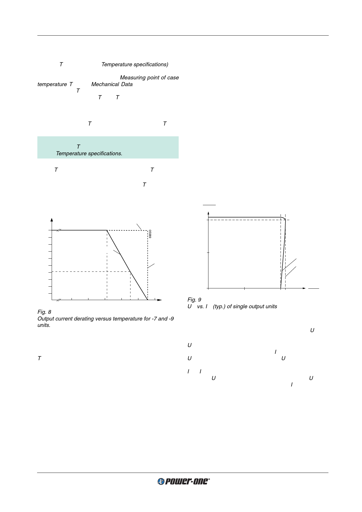
For -7 or -9 units at an ambient temperature TA of 85°C with
only convection cooling, the maximum permissible current
for each output is approx. 40% of its nominal value as per
figure.
Io/Io nom
Forced cooling
1.0
0.9
0.8
0.7
Convection cooling
0.6
0.5
TC max
0.4
0.3
0.2
0.1
0
TA min
50
60 70
80
90 100 TA [°C]
Fig. 8
Output current derating versus temperature for -7 and -9
units.
Thermal Protection
A temperature sensor generates an internal inhibit signal
which disables the outputs if the case temperature exceeds
TC max. The outputs are automatically re-enabled if the tem-
perature drops below this limit.
It is recommended that continuous operation under simul-
taneous extreme worst case conditions of the following
three parameters be avoided: Minimum input voltage,
maximum output power and maximum temperature.
Output Protection
Each output is protected against overvoltage which could
occur due to a failure of the control circuit by means of a
voltage suppressor diode which, under worst case condi-
tions, may become a short circuit. The suppressor diodes
are not designed to withstand externally applied over-
voltages. Overload at any of the two outputs will cause a
shut-down of both outputs. A red LED indicates the over-
load condition.
Parallel or Series Connection of Units
Single or double output units with equal nominal output volt-
age can be connected in parallel without any precautions
using option T.
With option T (current sharing), all units share the current
approximately equally.
Single output units and/or main and second outputs of dou-
ble output units can be connected in series with any other
(similar) output.
Note:
– Parallel connection of double output units should always
include both, main and second output to maintain good
regulation of both outputs.
– Not more than 5 units should be connected in parallel.
– Series connection of second outputs without involving
their main outputs should be avoided as regulation may
be poor.
– The maximum output current is limited by the output with
the lowest current limitation if several outputs are con-
nected in series.
Output Voltage Regulation of Single or Double Output
Modules with Outputs 1 and 2 Connected in Series
Uo
Uo nom
05001
0.98
0.5
Io1
IoL
0
0.5
1.0
Fig. 9
Uo1 vs. Io1 (typ.) of single output units
Io
Io nom
Output Voltage Regulation of Double Output Modules
Output 1 is under normal conditions regulated to Uo1 nom,
independent of the output currents.
Uo2 is dependent upon the load distribution. If both outputs
are loaded with more than 10% of Io nom, the deviation of
Uo2 remains within ±5% of the value of Uo1. The following 3
figures show the regulation with varying load distribution. If
Io1 = Io2 or the two outputs are connected in series, the de-
viation of Uo2 remains within ±1% of the value of Uo1 pro-
vided that a total load of more than 10% of Io nom is applied.
Two outputs of a single S 5000 module connected in paral-
lel will behave like the output of a S 4000 module; the paral-
leled output is fully regulated. No precautions are neces-
sary in using the R-input and the test sockets.
Edition 01/01.2001
9/27
Share Link: 