LT1253C 查看數據表(PDF) - Linear Technology
零件编号
产品描述 (功能)
生产厂家
LT1253C Datasheet PDF : 8 Pages
| |||
LT1253/LT1254
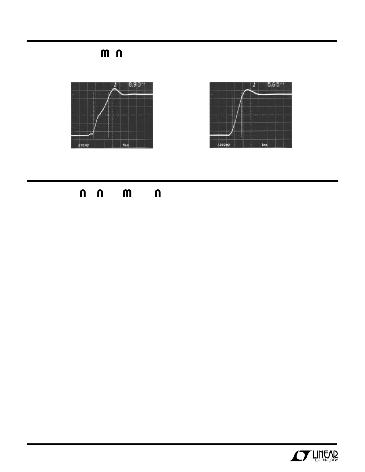
TYPICAL PERFOR A CE CHARACTERISTICS
Transient Response
Transient Response
VS = ±5V
AV = 1
RL = 150Ω
RF = 787Ω
VO = 1V
LT1253/54 • TPC16
RF = 562Ω VS = ±5V
RG = 61.9Ω AV = 10
VO = 1.5V RL = 150Ω
LT1253/54 • TPC17
UU W U
APPLICATIO S I FOR ATIO
Power Dissipation
The LT1253/LT1254 amplifiers combine high speed and
large output current drive into very small packages. Be-
cause these amplifiers work over a very wide supply range,
it is possible to exceed the maximum junction temperature
under certain conditions. To insure that the LT1253/
LT1254 are used properly, we must calculate the worst
case power dissipation, define the maximum ambient
temperature, select the appropriate package and then
calculate the maximum junction temperature.
The worst case amplifier power dissipation is the total of
the quiescent current times the total power supply voltage
plus the power in the IC due to the load. The quiescent
supply current of the LT1253/LT1254 has a strong nega-
tive temperature coefficient. The supply current of each
amplifier at 150°C is less than 7mA and typically is only
4.5mA. The power in the IC due to the load is a function of
the output voltage, the supply voltage and load resistance.
The worst case occurs when the output voltage is at half
supply, if it can go that far, or its maximum value if it
cannot reach half supply.
For example, let’s calculate the worst case power dissipa-
tion in a video cable driver operating on a ±12V supply that
delivers a maximum of 2V into 150Ω.
PDMAX = 2 × VS × ISMAX + (VS – VOMAX) × VOMAX/RL
PDMAX = 2 × 12V × 7mA + (12V – 2V) × 2V/150
= 0.168 + 0.133 = 0.301 Watt per Amp
Now if that is the dual LT1253, the total power in the
package is twice that, or 0.602W. We now must calculate
how much the die temperature will rise above the ambient.
The total power dissipation times the thermal resistance of
the package gives the amount of temperature rise. For the
above example, if we use the S8 surface mount package,
the thermal resistance is 150°C/W junction to ambient in
still air.
Temperature Rise = PDMAX × RθJA = 0.602W
× 150°C/W = 90.3°C
The maximum junction temperature allowed in the plastic
package is 150°C. Therefore the maximum ambient al-
lowed is the maximum junction temperature less the
temperature rise.
Maximum Ambient = 150°C – 90.3°C = 59.7°C
Note that this is less than the maximum of 70°C that is
specified in the absolute maximum data listing. In order to
use this package at the maximum ambient we must lower
the supply voltage or reduce the output swing.
6
Share Link: 