LT1618 查看數據表(PDF) - Linear Technology
零件编号
产品描述 (功能)
生产厂家
LT1618 Datasheet PDF : 16 Pages
| |||
LT1618
APPLICATIONS INFORMATION
Setting Output Voltage
To set the output voltage, select the values of R1 and R2
(see Figure 1) according to the following equation.
R1 =
R2
⎛
⎝⎜
VOUT
1.263
–
⎞
1⎠⎟
For current source applications, use the FB pin for over-
voltage protection. Pick R1 and R2 so that the output
voltage will not go too high if the load is disconnected or
if the load current drops below the preset value. Typically
choose R1 and R2 so that the overvoltage value will be
about 20% to 30% higher than the normal output voltage
(when in constant-current mode). This prevents the volt-
age loop from interfering with the current loop in current
source applications. For battery charger applications, pick
the values of R1 and R2 to give the desired end of charge
voltage.
Selecting RSENSE/Current Sense Adjustment
Use the following formula to choose the correct current
sense resistor value (for constant current operation).
RSENSE = 50mV/IMAX
For designs needing an adjustable current level, the IADJ
pin is provided. With the IADJ pin tied to ground, the
nominal current sense voltage is 50mV (appearing be-
tween the ISP and ISN pins). Applying a positive DC
voltage to the IADJ pin will decrease the current sense
voltage according to the following formula:
VISENSE
=
1.263V
– (0.8)VIADJ
25
For example, if 1V is applied to the IADJ pin, the current
sense voltage will be reduced to about 18mV. This
adjustability allows the regulated current to be reduced
without changing the current sense resistor (e.g. to adjust
brightness in an LED driver or to reduce the charge current
in a battery charger). If the IADJ pin is taken above 1.6V,
the output of the error amplifier (the VC pin) will be pulled
down and the LT1618 will stop switching.
A pulse width modulated (PWM) signal can also be used
to adjust the current sense voltage; simply add an RC
filterto convert the PWM signal into a DC voltage for the
IADJ pin. If the IADJ pin is not used, it should be tied to
ground. Do not leave the pin floating.
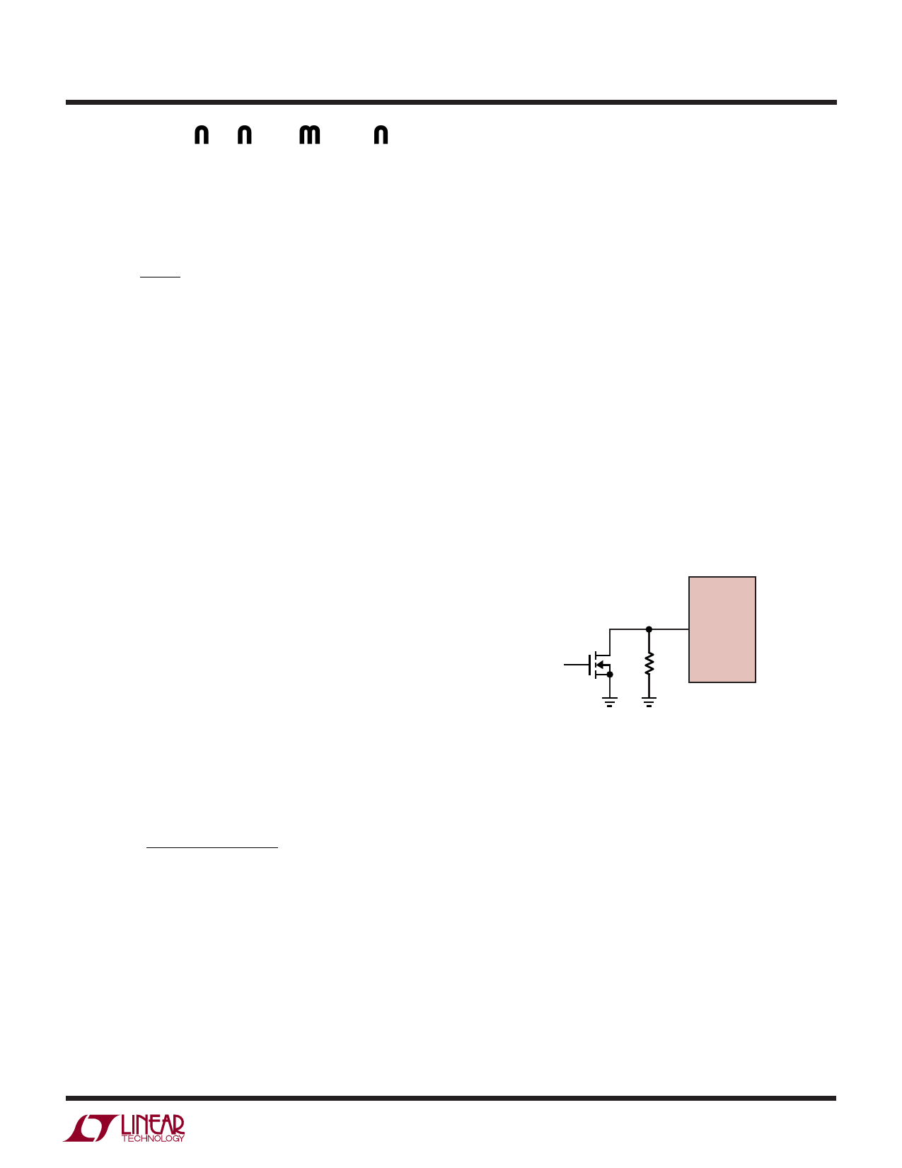
For applications needing only a simple one-step current
sense adjustment, the circuit in Figure 2 works well. If a
large value resistor (≥2MΩ) is placed between the IADJ pin
and ground, the current sense voltage will reduce to about
25mV, providing a 50% reduction in current. Do not leave
the IADJ pin open. This method gives a well-regulated
current value in both states, and is controlled by a logic
signal without the need for a variable PWM or DC control
signal. When the NMOS transistor is on, the current sense
voltage will be 50mV, when it is off, the current sense
voltage will be reduced to 25mV.
LT1618
FULL
CURRENT
IADJ
2M
1618 F02
Figure 2
Considerations When Sensing Input Current
In addition to regulating the DC output current for current-
source applications, the constant-current loop of the
LT1618 can also be used to provide an accurate input
current limit. Boost converters cannot provide output
short-circuit protection, but the surge turn-on current can
be drastically reduced using the LT1618’s current sense
at the input. SEPICs, however, have an output that is DC-
isolated from the input, so an input current limit not only
helps soft-start the output but also provides excellent
short-circuit protection.
sn1618 1618fas
7
Share Link: 