LT3572 查看數據表(PDF) - Linear Technology
零件编号
产品描述 (功能)
生产厂家
LT3572 Datasheet PDF : 12 Pages
| |||
LT3572
APPLICATIONS INFORMATION
PWM
The LT3572 can PWM the output drivers at a very high
frequency. The limitation on the frequency is determined
by the internal rise in die temperature that occurs when
driving the motor. The power delivered to the piezo motor
is propotional to VOUT2, the capacitance of the motor, and
the PWM frequency. When any of these are increased the
power dissipated in the part increases causing the internal
die temperature to increase. Driving two 2.2nF capacitors
with VOUT at 30V, the maximum PWM frequency should be
less than 80 kHz. The LT3572 can run at a higher frequency
but either VOUT needs to be reduced or the capacitance
needs to be lowered. A piezo motor has an associated
capacitance that cannot be reduced so the output voltage
must be lowered. Since the power is proportional to VOUT2 a
reduction of VOUT to 25V from 30V will allow the LT3572 to
run at a maxim frequency of 115 kHz. If a different motor is
used the maximum PWM frequency will need to be adjusted
inversely to the equivolent capacitance of the motor.
Inductor Selection
A 10μH inductor is recommended for most LT3572 ap-
plications. Choose an inductor that will handle at least
1A without saturating, and ensure that the inductor has a
low DCR (copper-wire resistance) to minimize I2R power
losses. Table 1 lists several inductor manufacturers.
Table 1. Inductor Manufacturers
Sumida
(847) 956-0666
TDK
(847) 803-6100
Murata
(714) 852-2001
FDK
(408) 432-8331
www.sumida.com
www.tdk.com
www.murata.com
www.tdk.co.jp
Capacitor Selection
The small size of ceramic capacitors makes them ideal
for LT3572 applications. Only X5R or X7R types should
be used because they retain their capacitance over wider
voltage and temperature ranges than other types such as
Y5V or Z5U. A 4.7μF to 15μF output capacitor is sufficient
for stable transient response, however, more output ca-
pacitance can help limit the voltage droop on VOUT during
transients.
Ceramic capacitors also make a good choice for the input
decoupling capacitor, which should be placed as close as
possible to the LT3572. A 1μF to 4.7μF input capacitor
is sufficient for most applications. Table 2 shows a list
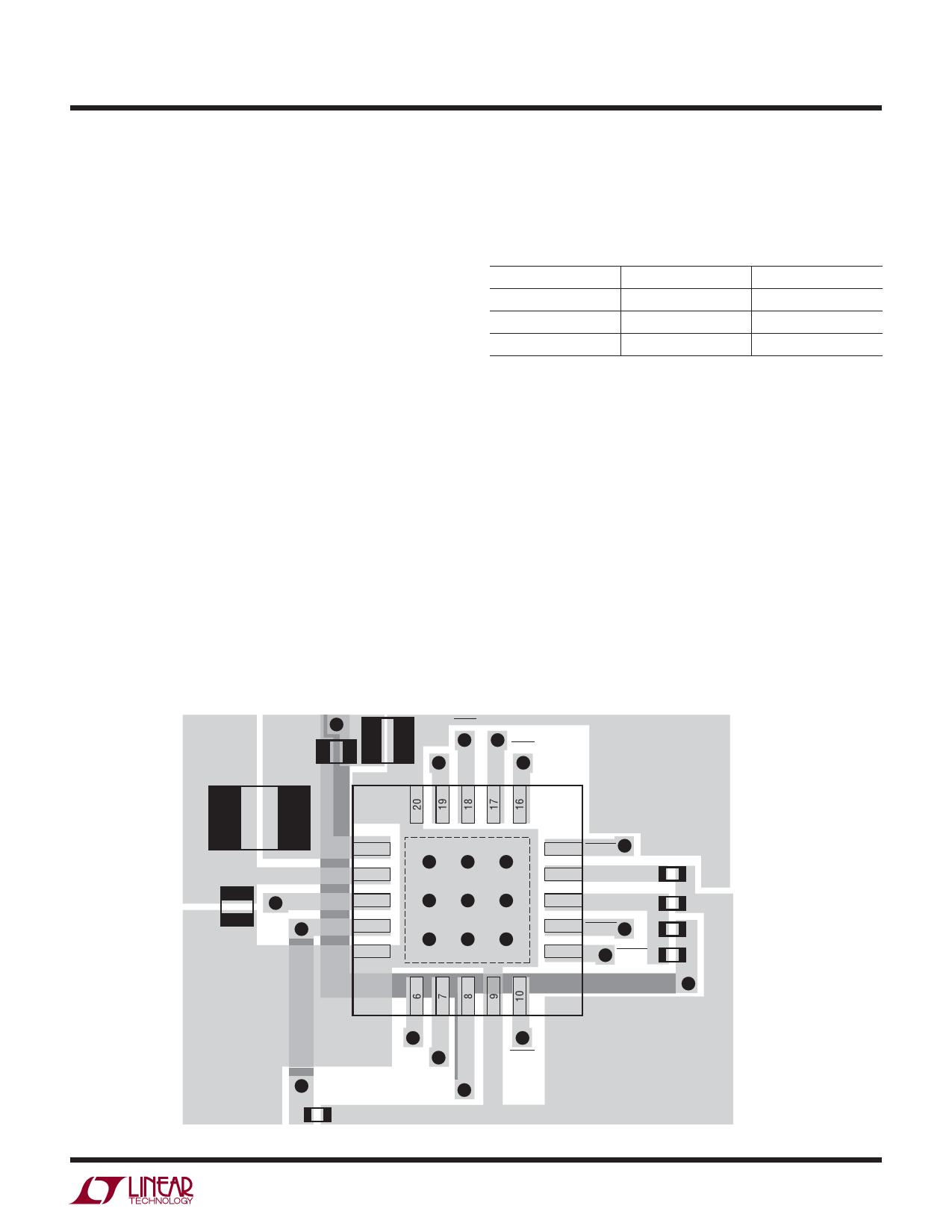
OUTA OUTB
D1
OUTA
OUTB
C1
L1
C3
SW 1
VIN 2
SYNC 3
RT 4
GND 5
15 PGOOD
C2
14 SS
GND
R2
13 FB
R1
12 SHDNB
11
SHDNA
CFF
PWMB
PWMA
SHDN
R4
VOUT
3572 BD LAYOUT
3572fa
9
Share Link: 