LTC1148CN 查看數據表(PDF) - Linear Technology
零件编号
产品描述 (功能)
生产厂家
LTC1148CN Datasheet PDF : 20 Pages
| |||
UU W U
APPLICATIO S I FOR ATIO
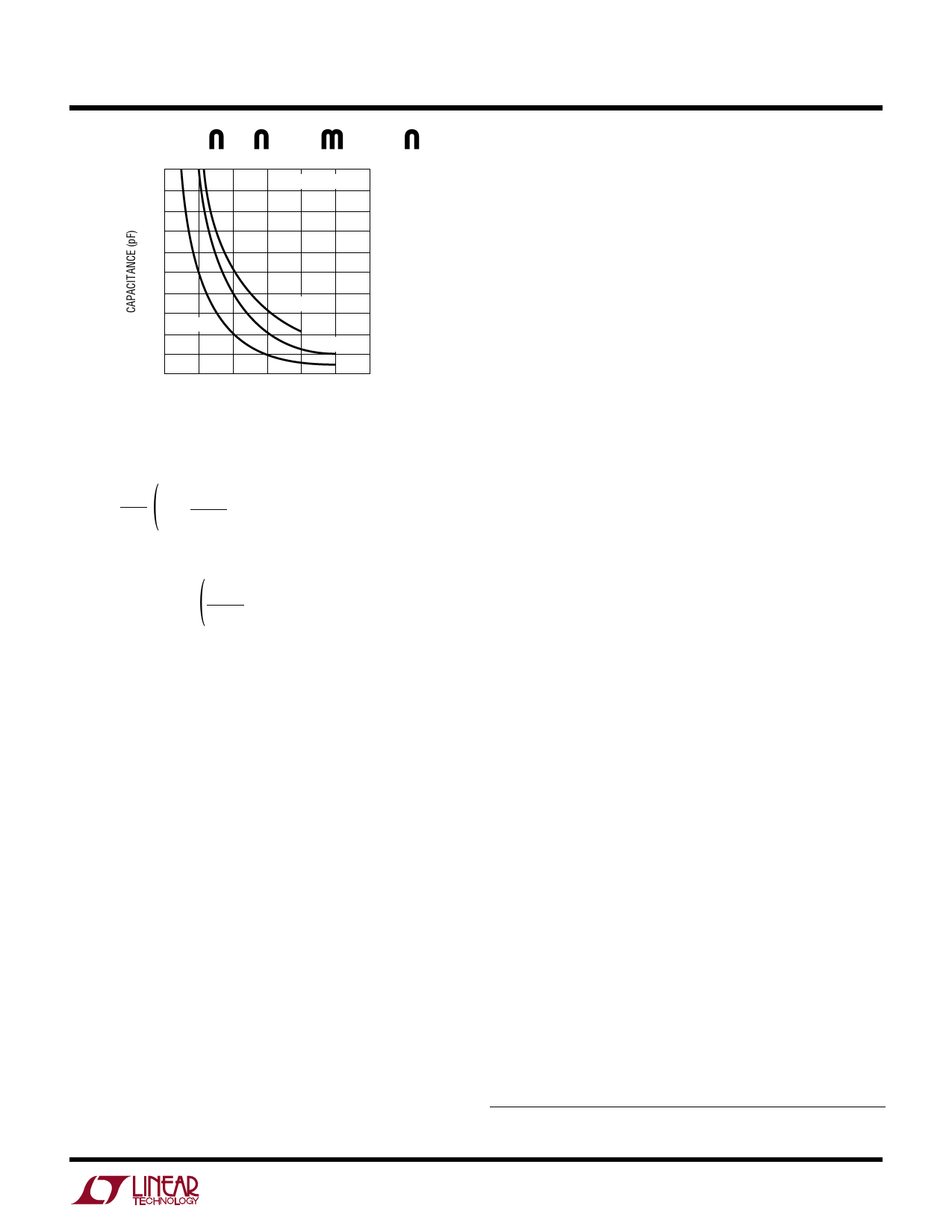
1000
VSENSE– = VOUT = 5V
800
600
400
VIN = 7V
200
VIN = 12V
VIN = 10V
0
0
100
200
300
FREQUENCY (kHz)
LTC1148 • F03
Figure 3. Timing Capacitor Value
) f = 1 1 – VOUT
tOFF
VIN
where:
) tOFF = 1.3(104)CT
VREG
VOUT
VREG is the desired output voltage (i.e., 5V, 3.3V). VOUT is
the measured output voltage. Thus VREG/VOUT = 1 in
regulation.
Note that as VIN decreases, the frequency decreases.
When the input to output voltage differential drops
below 1.5V, the LTC1148 series reduces tOFF by in-
creasing the discharge current in CT. This prevents
audible operation prior to dropout.
Once the frequency has been set by CT, the inductor L
must be chosen to provide no more than 25mV/RSENSE
of peak-to-peak inductor ripple current. This results in
a minimum required inductor value of:
LMIN = 5.1(105)RSENSE(CT)VREG
As the inductor value is increased from the minimum
value, the ESR requirements for the output capacitor
are eased at the expense of efficiency. If too small an
inductor is used, the inductor current will decrease past
zero and change polarity. A consequence of this is that
the LTC1148 series may not enter Burst Mode operation
and efficiency will be severely degraded at low currents.
LTC1148
LTC1148-3.3/LTC1148-5
Inductor Core Selection
Once the minimum value for L is known, the type of
inductor must be selected. The highest efficiency will be
obtained using ferrite, Kool Mµ® on molypermalloy (MPP)
cores. Lower cost powdered iron cores provide suitable
performance but cut efficiency by 3% to 7%. Actual core
loss is independent of core size for a fixed inductor value,
but it is very dependent on inductance selected. As induc-
tance increases, core losses go down. Unfortunately,
increased inductance requires more turns of wire and
therefore copper losses increase.
Ferrite designs have very low core loss, so design goals
can concentrate on copper loss and preventing saturation.
Ferrite core material saturates “hard,” which means that
inductance collapses abruptly when the peak design cur-
rent is exceeded. This results in an abrupt increase in
inductor ripple current and consequent output voltage
ripple which can cause Burst Mode operation to be falsely
triggered. Do not allow the core to saturate!
Kool Mµ (from Magnetics, Inc.) is a very good, low loss
core material for toroids, with a “soft” saturation charac-
teristic. Molypermalloy is slightly more efficient at high
(>200kHz) switching frequencies, but quite a bit more
expensive. Toroids are very space efficient, especially
when you can use several layers of wire. Because they
generally lack a bobbin, mounting is more difficult. How-
ever, new designs for surface mount are available from
Coiltronics and Beckman Industrial Corp. which do not
increase the height significantly.
Power MOSFET and D1 Selection
Two external power MOSFETs must be selected for use
with the LTC1148 series: a P-channel MOSFET for the
main switch, and an N-channel MOSFET for the synchro-
nous switch. The main selection criteria for the power
MOSFETs are the threshold voltage VGS(TH) and on resis-
tance RDS(ON).
The minimum input voltage determines whether standard
threshold or logic-level threshold MOSFETs must be used.
For VIN > 8V, standard threshold MOSFETs (VGS(TH) < 4V)
may be used. If VIN is expected to drop below 8V, logic-
Kool Mµis a registered trademark of Magnetics, Inc.
9
Share Link: 