LTC1159 查看數據表(PDF) - Linear Technology
零件编号
产品描述 (功能)
生产厂家
LTC1159 Datasheet PDF : 20 Pages
| |||
LTC1159
LTC1159-3.3/LTC1159-5
APPLICATIO S I FOR ATIO
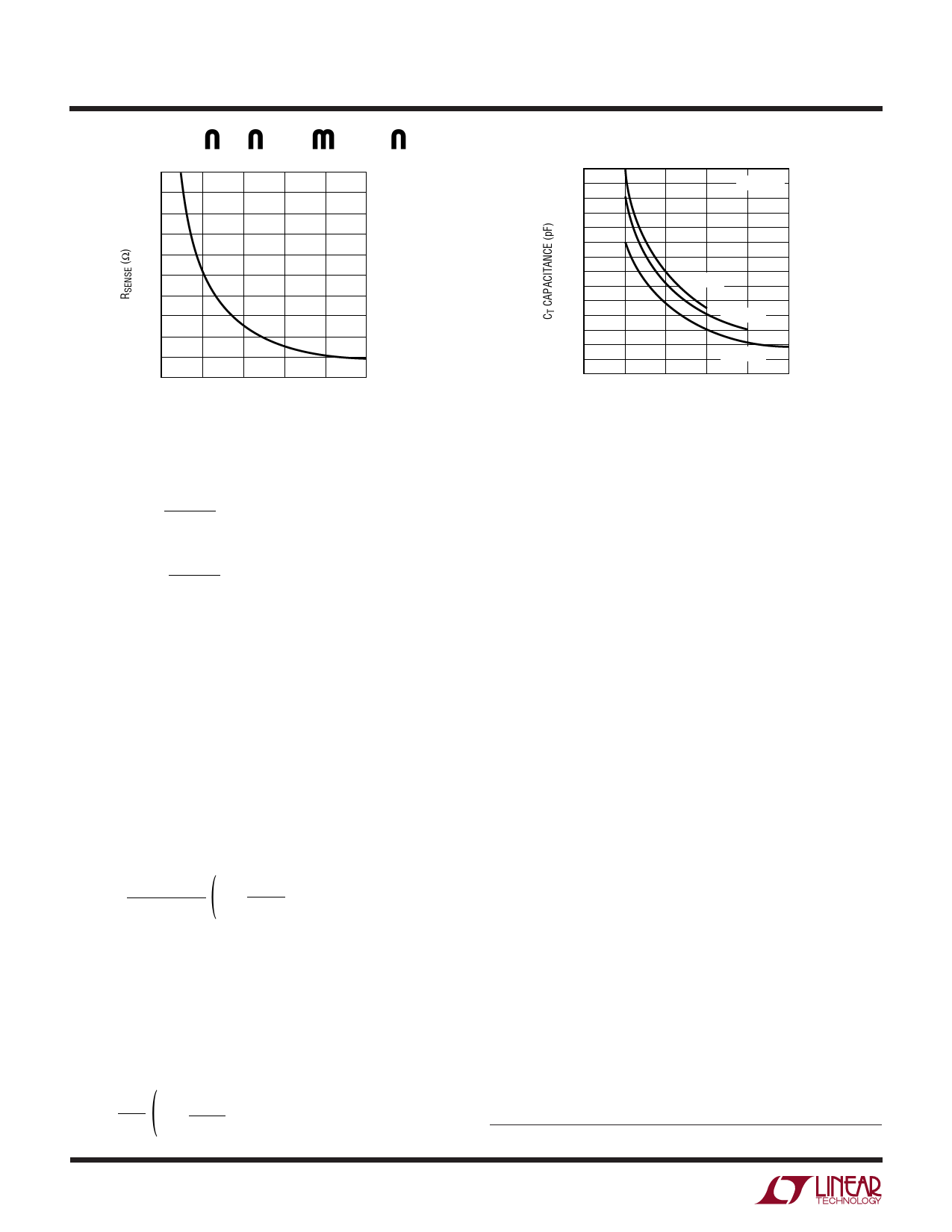
0.20
0.18
0.16
0.14
0.12
0.10
0.08
0.06
0.04
0.02
0
0
1
2
3
4
5
MAXIMUM OUTPUT CURRENT (A)
LTC1159 • F02
Figure 2. RSENSE vs Maximum Output Current
IBURST
≈
15mV
RSENSE
ISC(PK) =
150mV
RSENSE
The LTC1159 automatically extends tOFF during a short
circuit to allow sufficient time for the inductor current to
decay between switch cycles. The resulting ripple current
causes the average short-circuit current ISC(AVG) to be
reduced to approximately IMAX.
L and CT Selection for Operating Frequency
The LTC1159 uses a constant off-time architecture with
tOFF determined by an external timing capacitor CT. The
value of CT is calculated from the desired continuous mode
operating frequency, f:
) CT =
7.8 • 10–5
f
1–
VOUT
VIN
A graph for selecting CT versus frequency including the
effects of input voltage is given in Figure 3.
As the operating frequency is increased the gate charge
losses will be higher, reducing efficiency (see Efficiency
Considerations). The complete expression for operating
frequency is given by:
) f = 1 1 – VOUT
tOFF
VIN
1400
1200
1000
800
600
400
200
0
0
VOUT = 5V
VIN = 48V
VIN = 24V
VIN = 12V
50 100 150 200 250
FREQUENCY (kHz)
LTC1159 • F03
Figure 3. Timing Capacitor Selection
where tOFF = 1.3 • 104 • CT
Once the frequency has been set by CT, the inductor L
must be chosen to provide no more than 0.025V/RSENSE
of peak-to-peak inductor ripple current. This results in a
minimum required inductor value of:
LMIN = 5.1 • 105 • RSENSE • CT • VREG
As the inductor value is increased from the minimum value,
the ESR requirements for the output capacitor are eased at
the expense of efficiency. If too small an inductor is used,
the LTC1159 may not enter Burst Mode operation and
efficiency will be severely degraded at low currents.
Inductor Core Selection
Once the minimum value for L is known, the type of
inductor must be selected. High efficiency converters
generally cannot afford the core loss found in low cost
powdered iron cores, forcing the use of more expensive
ferrite, molypermalloy or Kool Mµ® cores. Actual core loss
is independent of core size for a fixed inductor value, but
it is very dependent on the inductance selected. As induc-
tance increases, core losses go down but copper (I2R)
losses will increase.
Ferrite designs have very low core loss, so design goals can
concentrate on copper loss and preventing saturation.
Ferrite core material saturates “hard,” which means that
inductance collapses abruptly when the peak design cur-
rent is exceeded. This results in an abrupt increase in
Kool Mµ is a registered trademark of Magnetics, Inc.
8
Share Link: 