LTC1164C 查看數據表(PDF) - Linear Technology
零件编号
产品描述 (功能)
生产厂家
LTC1164C Datasheet PDF : 16 Pages
| |||
LTC1164
APPLICATIO S I FOR ATIO
ANALOG CONSIDERATIONS
1. Grounding and Bypassing
The LTC1164 should be used with separated analog
and digital ground planes and single point grounding
techniques.
Pin 6 (AGND) should be tied directly to the analog ground
plane.
Pin 7 (V+) should be bypassed to the ground plane with a
0.1µF ceramic disk with leads as short as possible. Pin 19
(V–) should be bypassed with a 0.1µF ceramic disk. For
single supply applications, V– can be tied to the analog
ground plane.
For good noise performance, V+ and V– must be free of
noise and ripple.
All analog inputs should be referenced directly to the
single point ground. The clock inputs should be shielded
from and/or routed away from the analog circuitry and a
separate digital ground plane used.
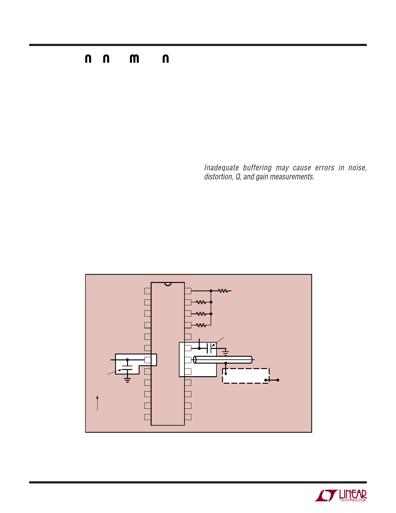
Figure 3 shows an example of an ideal ground plane design
for a two sided board. Of course this much ground
plane will not always be possible, but users should strive
to get as close to this as possible. Proto boards are not
recommended.
2. Buffering the Filter Output
When driving coaxial cables and 1x scope probes, the filter
output should be buffered. This is important
especially when high Qs are used to design a specific filter.
Inadequate buffering may cause errors in noise,
distortion, Q, and gain measurements. When 10x probes
are used, buffering is usually not required. A buffer is
recommended especially when THD tests are performed.
As shown in Figure 4, the buffer should be adequately
bypassed to minimize clock feedthrough.
8
7.5V
0.1µF
CERAMIC
DISK
ANALOG
GROUND
PLANE
1 • PIN 1 DENT 24
2
23
3
22
4
21
5
20 –7.5V
6
19
7
18
8
17
9
16
10
15
11
14
12
13
VIN
FOR BEST HIGH FREQUENCY RESPONSE
PLACE RESISTORS PARALLEL TO DOUBLE
SIDED COPPER CLAD BOARD AND LAY FLAT
(4 RESISTORS SHOWN HERE TYPICAL)
0.1µF CERAMIC DISK
CLOCK
DIGITAL GROUND
PLANE
(SINGLE POINT
GROUND)
NOTE: CONNECT ANALOG AND DIGITAL
GROUND PLANES AT A SINGLE POINT AT
THE BOARD EDGE
Figure 3. Example Ground Plane Breadboard Technique for LTC1164
LTC1164 • AI01
1164fa
Share Link: 