LTC1700EMS 查看數據表(PDF) - Linear Technology
零件编号
产品描述 (功能)
生产厂家
LTC1700EMS Datasheet PDF : 16 Pages
| |||
LTC1700
APPLICATIONS INFORMATION
To eliminate this subharmonic oscillation, a compensat-
ing ramp is added internally to the LTC1700 on the
inductor current waveform when the duty cycle exceeds
5%. This scheme, known as slope compensation, makes
the loop perceive that there is more inductor current than
it actually has. As a result, the maximum current capability
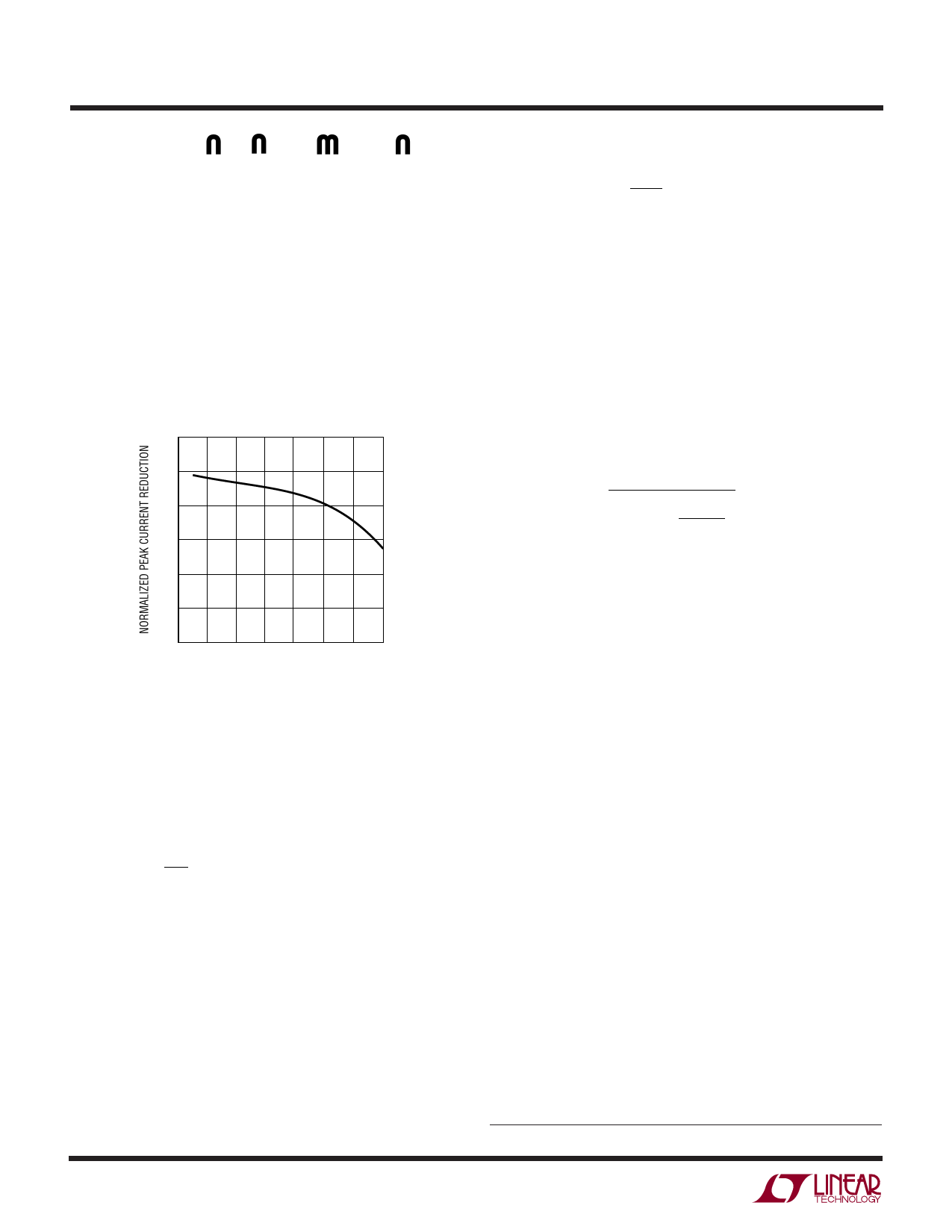
of the regulator is reduced. This reduction is proportional
to the duty cycle and is shown in Figure 5. Hence for
applications that operate at high duty cycles, the
N-channel MOSFET chosen should have a lower RDS(ON)
to make up for this reduction (See Design Example).
1.2
1.0
0.8
0.6
0.4
0.2
0
0 10 20 30 40 50 60 70
DUTY CYCLE (%)
1700 F05
Figure 5. Maximum Output Current vs Duty Cycle
Inductor Value Selection
Given the input voltage, inductor value and operating
frequency, the ripple current can be calculated:
∆IL=
VIN⎛⎝⎜
DC
fL
⎞⎠⎟
Lower ripple current reduces core losses in the inductor,
ESR losses in the output capacitors and output voltage
ripple. Thus, highest efficiency operation is obtained at
low frequency with small ripple current. To achieve this,
however, requires a larger inductor.
A reasonable starting point is to choose a ripple current
that is about 40% of IO(MAX). Note that the largest ripple
current occurs at the highest VIN. To guarantee that ripple
current does not exceed a specified maximum, the induc-
tor should be chosen according to:
10
LMIN≥
VIN(MAX) ⎛⎝⎜
DC
f∆IL
⎞
⎠⎟
With Burst Mode operation enabled on the LTC1700, the
ripple current is normally set such that the inductor
current is continuous during burst periods. Remember
that during bursting, the peak current is clamped at
approximately:
IBURST(PEAK) ≅ 36mV/RDS(ON)
Hence the peak-to-peak ripple selected for optimal burst
mode operation should not exceed IBURST(PEAK). This
implies a minimum inductance of:
( ) L MINBURST
=
VIN(MAX) DC
(f)(0.66)⎛⎝⎜
IOMAX
1– DC
⎞
⎠⎟
In applications that invoke Burst Mode operation, the
inductor should be chosen so it has low ripple (0.4IOMAX)
current during heavy load and continuous operation dur-
ing bursting. The criteria for selecting which equation to
use is:
Use LMIN for Duty Cycle > 36%
Use LMINBURST for Duty Cycle ≤ 36%
A smaller value than LMIN could be used in the circuit;
however, the inductor current will not be continuous
during burst periods. The advantage of using a smaller
inductance than LMIN is primarily size. The disadvantage is
higher output ripple.
Inductor Core Selection
Once the value for L is known, the type of inductor must be
selected. High efficiency converters generally cannot af-
ford the core loss found in low cost powdered iron cores,
forcing the use of more expensive ferrite, molypermalloy,
or Kool Mµ® cores. Actual core loss is independent of core
size for a fixed inductor value, but it is very dependent on
inductance selected. As inductance increases, core losses
go down. Unfortunately, increased inductance requires
more turns of wire and therefore copper losses will
increase. Ferrite designs have very low core losses and are
Kool Mµ is a registered trademark of Magnetics, Inc.
1700fa
Share Link: 