LTC1700EMS 查看數據表(PDF) - Linear Technology
零件编号
产品描述 (功能)
生产厂家
LTC1700EMS Datasheet PDF : 16 Pages
| |||
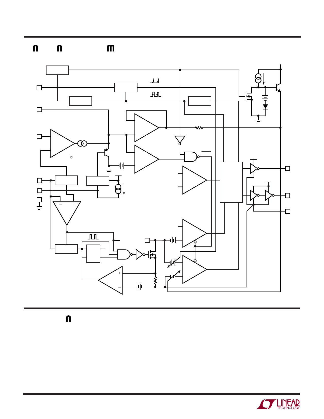
LTC1700
W
FUNCTIONAL DIAGRA
SYNC/
MODE
5
ITH 2
BURST
INHIBIT
X
Y Y = “0” ONLY WHEN X IS A CONSTANT “1”, OTHERWISE Y = “1”
SLOPE
COMP
MAIN
OSC
–
90% DUTY
CYCLE LIMIT
VFB 3
–
EA
1.205V +
gm = 0.9m
VOUT 7
RUN/SS 4
SGND 1
1.205V
REFERENCE
SC
+
RUN/
SOFT-START
0.12V
VOUT
–
BURST
+
3.8µA
VREF + 58mV
VFB
SLEEP
–
OV
+
VCC
0.36V
VOUT
SWITCHING
LOGIC
AND
BLANKING
CIRCUIT
VOUT
6 TG
8 BG
9 PGND
= “1” WHEN VOUT < 2.3V
START-UP
OSCILLATOR
S QB
L1
RQ
SHDN
ICMP
SW 10
VOUT
9mV
+
IRCMP
–
M1
+
VDS
–
1Ω
60mV
1700 • FD
U
OPERATIO (Refer to Functional Diagram)
Main Control Loop
The LTC1700 is a constant frequency, current mode
controller for DC/DC step-up converters. In normal opera-
tion, the main external N-channel power MOSFET is turned
on when the oscillator sets a latch and turned off either
when the VDS sense amplifier (VDS) resets the latch or the
duty cycle has reached 90%. When the main MOSFET is
turned off, the synchronous rectifier P-channel MOSFET is
6
turned on until either the inductor current is about to
reverse, as determined by the current reversal comparator
(IRCMP), or the next cycle begins. Inductor current is
measured by sensing the VDS potential across the con-
ducting MOSFET. The peak inductor current is controlled
by the voltage on the ITH pin, which is the output of the
error amplifier (EA). An external resistive divider con-
nected between VOUT and GND allows EA to receive an
1700fa
Share Link: 