LTC1700EMS 查看數據表(PDF) - Linear Technology
零件编号
产品描述 (功能)
生产厂家
LTC1700EMS Datasheet PDF : 16 Pages
| |||
LTC1700
ABSOLUTE AXI U RATI GS
(Note 1)
Output Supply Voltage (VOUT) .....................– 0.3V to 6V
RUN/SS, VFB Voltages ..............................– 0.3V to 2.4V
SYNC/MODE, ITH Voltages ...........................– 0.3V to 6V
SWITCH Voltage (SW) ..............................– 0.3V to 6.5V
TG, BG Peak Output Current (<10µs) ......................... 1A
Operating Temperature Range (Note 2) ...–40°C to 85°C
Junction Temperature (Note 3) ............................. 125°C
Storage Temperature Range ................. – 65°C to 150°C
Lead Temperature (Soldering, 10 sec).................. 300°C
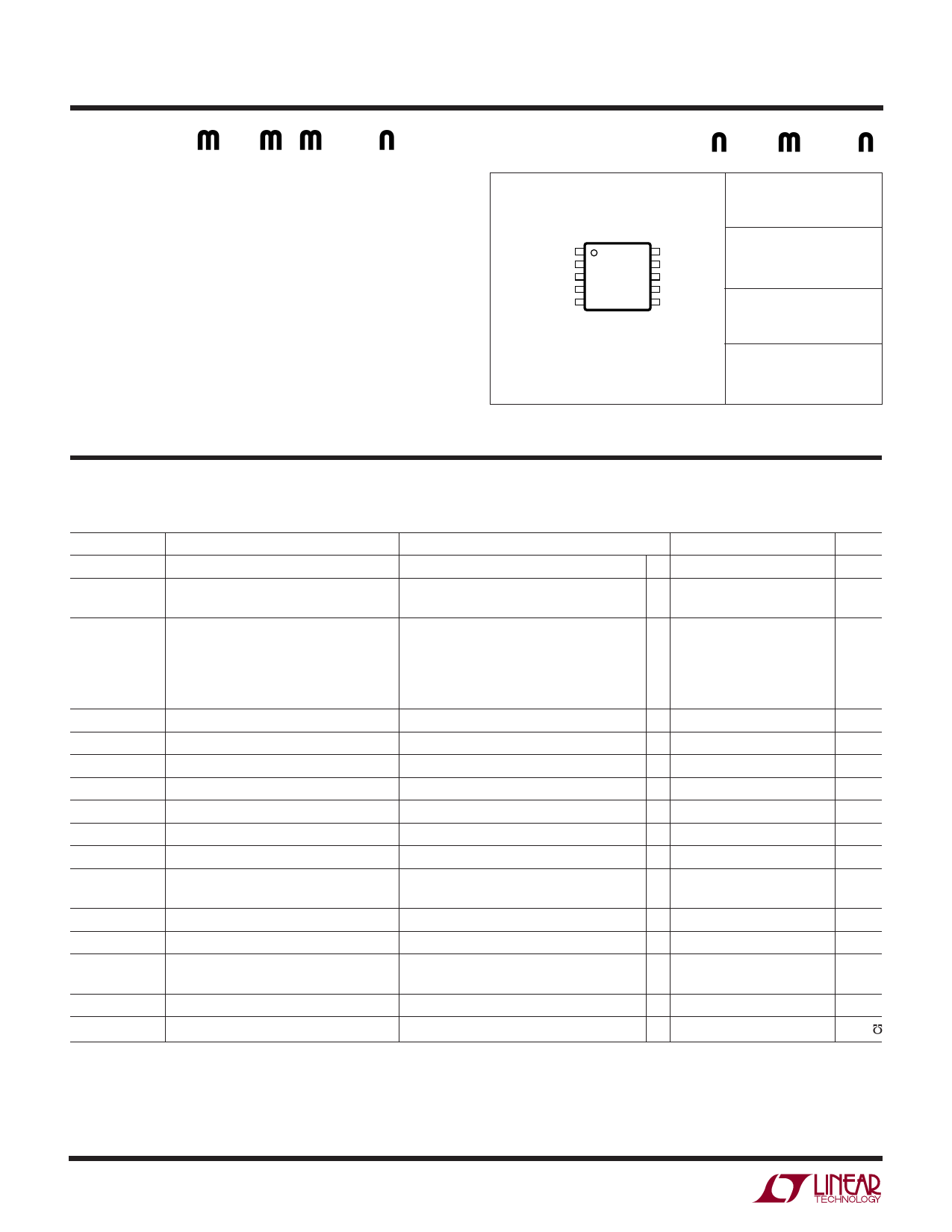
UW U
PACKAGE/ORDER I FOR ATIO
SGND 1
ITH 2
VFB 3
RUN/SS 4
SYNC/MODE 5
TOP VIEW
10 SW
9 PGND
8 BG
7 VOUT
6 TG
MS PACKAGE
10-LEAD PLASTIC MSOP
TJMAX = 125°C, θJA = 150°C/W
ORDER PART
NUMBER
LTC1700EMS
MS PART
MARKING
LTLC
Consult LTC Marketing for parts specified with wider operating temperature ranges.
ELECTRICAL CHARACTERISTICS The ● denotes the specifications which apply over the full operating
temperature range, otherwise specifications are at TA = 25°C. VOUT = 3V unless otherwise specified.
SYMBOL
VSOP
VOP
IS
IVFB
VFB
∆VOSENS
VLOADREG
VOVL
VRUN/SS
IRUN/SS
fOSC
VSYNC/MODE
DC MAX
∆VSENSE(MAX)
PARAMETER
Start-Up Minimum Operating Voltage
Minimum Operating Voltage
Hysteresis
Input DC Supply Current
Normal Mode
Sleep Mode
Start-Up Mode
Shutdown
Feedback Current
Regulated Output Voltage
Reference Voltage Line Regulation
Output Voltage Load Regulation
Output Overvoltage Lockout
Shutdown Threshold
Soft-Start Current Source
Oscillator Frequency
Start-Up Oscillator Frequency
SYNC/MODE Threshold
Maximum Duty Cycle
Maximum Current Sense Voltage
CONDITIONS
MIN
(Note 4)
(Note 5) VOUT Ramping Up
(Note 6)
VFB = 1.6V, VMODE = 0V, VRUN/SS = 3V
VFB = 1.6V, VMODE = 3V, VRUN/SS = 3V
VFB = 0V, VMODE, VRUN/SS, VOUT = 1.8V
VFB = 0V, VMODE = 3V, VRUN/SS = 0V
VFB = 1.20V
(Note 7)
●
VIN = 2.7V to 5V (Note 7)
Measured in Servo Loop; VITH = 0.3V to 0.9V
Reference to Nominal VFB
VRUN/SS Ramping Up
●
VRUN/SS = 0V
VOUT = 4.2V
●
VOUT = 1.8V, VRUN/SS = 1.8V, VSW = 1.1V
VSYNC/MODE Ramping Down from 1.2V
fOSC = 550kHz
●
1.187
2.5
0.7
2
460
150
1.03
84
55
63
TYP
0.9
2.34
90
536
179
35
10
1
1.205
0.0106
0.036
4.8
1.09
3.79
530
225
1.13
88
78
MAX
1.8
2.6
620
210
45
14
50
1.223
0.080
0.065
9
1.2
6
680
1.25
92
100
UNITS
V
V
mV
µA
µA
µA
µA
nA
V
%/V
%
%
V
µA
kHz
kHz
V
%
mV
mV
ILIMIT
gm
Current Limit At Start-Up
Transconductance of Error Amplifier
VOUT = 1.8V
VFB = VREF ± 10mV
40
60
mA
0.65
0.9
1.30
m
1700fa
2
Share Link: 