LTM2881 ТЪЦуюІТЋИТЊџУАе№╝ѕPDF№╝Ѕ - Linear Technology
жЏХС╗Ху╝ќтЈи
С║ДтЊЂТЈЈУ┐░ (тіЪУЃй)
ућЪС║Дтјѓт«Х
LTM2881 Datasheet PDF : 24 Pages
| |||
LTM2881
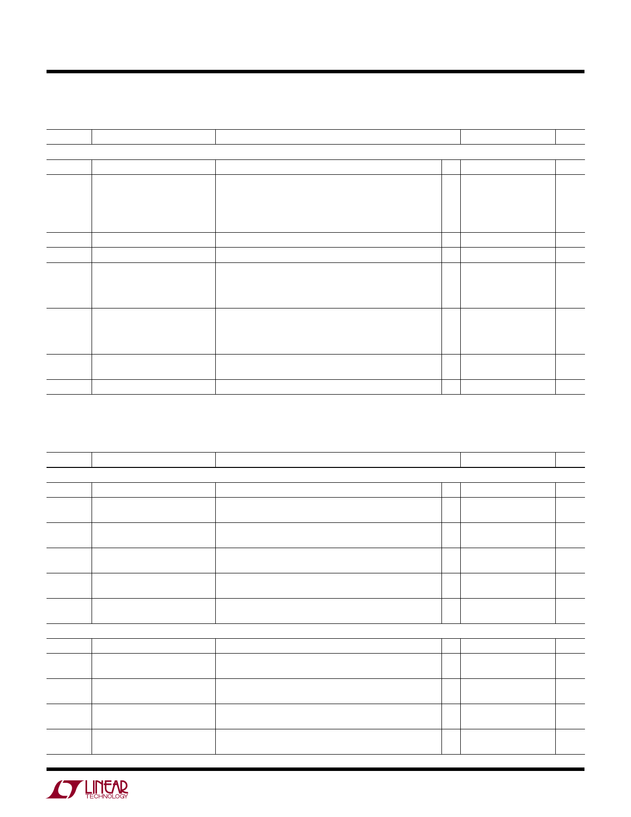
Electrical Characteristics The l denotes the specifications which apply over the full operating
temperature range, otherwise specifications are at TA = 25┬░C. LTM2881-3 VCC = 3.3V, LTM2881-5 VCC = 5.0V, VL = 3.3V, GND = GND2 =
0V, ON = VL unless otherwise noted.
SYMBOL PARAMETER
CONDITIONS
MIN TYP MAX UNITS
Logic
VIL
Logic Input Low Voltage
1.62V РЅц VL РЅц 5.5V
VIH
DIN
Logic Input High Voltage
SLO
DI, TE, DE, ON, RE:
VL РЅЦ 2.35V
1.62V РЅц VL < 2.35V
IINL
Logic Input Current
VHYS
Logic Input Hysteresis
(Note 2)
VOH
Output High Voltage
Output High, ILOAD = РђЊ4mA
(Sourcing), 5.5V РЅЦ VL РЅЦ 3V
Output High, ILOAD = РђЊ1mA
(Sourcing), 1.62V РЅц VL < 3V
VOL
Output Low Voltage
Output Low, ILOAD = 4mA
(Sinking), 5.5V РЅЦ VL РЅЦ 3V
Output High, ILOAD = 1mA
(Sinking), 1.62V РЅц VL < 3V
IOZR
Three-State (High Impedance) RE = VL, 0V РЅц RO РЅц VL
Output Current on RO
l
l 0.67РђбVCC2
l
2
0.4
V
V
V
l 0.67РђбVL
V
l 0.75РђбVL
V
l
0 ┬▒1
┬хA
150
mV
l VL РђЊ0.4
V
l VL РђЊ0.4
V
l
0.4
V
l
0.4
V
l
┬▒1
┬хA
IOSR
Short-Circuit Current
0V РЅц (RO or DOUT) РЅц VL
l
┬▒85
mA
switching Characteristics The l denotes the specifications which apply over the full operating
temperature range, otherwise specifications are at TA = 25┬░C. LTM2881-3 VCC = 3.3V, LTM2881-5 VCC = 5.0V, VL = 3.3V, GND = GND2 =
0V, ON = VL unless otherwise noted.
SYMBOL PARAMETER
CONDITIONS
MIN TYP MAX UNITS
Driver SLO = VCC2
fMAX
Maximum Data Rate
(Note 3)
20
Mbps
tPLHD
tPHLD
Driver Input to Output
RDIFF = 54╬Е, CL = 100pF
(Figure 4)
l
60 85
ns
РѕєtPD
Driver Input to Output Difference RDIFF = 54╬Е, CL = 100pF
|tPLHD РђЊ tPHLD|
(Figure 4)
l
18
ns
tSKEWD
Driver Output Y to Output Z
RDIFF = 54╬Е, CL = 100pF
(Figure 4)
l
1 ┬▒8
ns
tRD
Driver Rise or Fall Time
tFD
tZLD, tZHD, Driver Output Enable or Disable
tLZD, tHZD Time
Driver SLO = GND2
RDIFF = 54╬Е, CL = 100pF
(Figure 4)
RL = 500╬Е, CL = 50pF
(Figure 5)
l
4 12.5
ns
l
170
ns
fMAX
tPLHD
tPHLD
РѕєtPD
tSKEWD
Maximum Data Rate
Driver Input to Output
Driver Input to Output Difference
|tPLHD РђЊ tPHLD|
Driver Output Y to Output Z
(Note 3)
RDIFF = 54╬Е, CL = 100pF
(Figure 4)
RDIFF = 54╬Е, CL = 100pF
(Figure 4)
RDIFF = 54╬Е, CL = 100pF
(Figure 4)
250
kbps
1 1.55
┬хs
50 500
ns
┬▒200 ┬▒500
ns
tRD
Driver Rise or Fall Time
tFD
RDIFF = 54╬Е, CL = 100pF
(Figure 4)
l
0.9 1.5
┬хs
2881fh
For more information www.linear.com/LTM2881
5
Share Link: 