M24164-BN3 查看數據表(PDF) - STMicroelectronics
零件编号
产品描述 (功能)
生产厂家
M24164-BN3 Datasheet PDF : 16 Pages
| |||
M24164
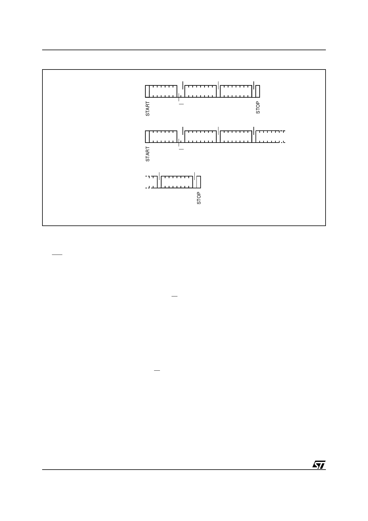
Figure 8. Write Modes Sequence
BYTE WRITE
PAGE WRITE
ACK
ACK
ACK
DEV SEL
BYTE ADDR
DATA IN
R/W
ACK
ACK
ACK
DEV SEL
BYTE ADDR DATA IN 1
DATA IN 2
R/W
ACK
ACK
DATA IN N
AI01941
Read Operations
Read operations are independent from the state of
the WC input pin. On delivery, the memory contents
is set at all "1’s" (or FFh).
Current Address Read. The memory has an inter-
nal byte address counter. Each time a byte is read,
this counter is incremented. For the Current Ad-
dress Read mode, following a START condition,
the master sends a Device Select code with the RW
bit set to ’1’. The memory acknowledges this and
outputs the byte addressed by the internal byte
address counter. This counter is then incremented.
The master have to NOT acknowledge the byte
output and terminates the transfer with a STOP
condition.
Random Address Read. A dummy write is per-
formed to load the memory address into the ad-
dress counter, see Figure 10. This is followed by
another START condition from the master and the
Device Select code is repeated with the RW bit set
to ’1’. The memory acknowledges this and outputs
the byte addressed. The master have to NOT ac-
knowledge the byte output and terminates the
transfer with a STOP condition.
Sequential Read. This mode can be initiated with
either a Current Address Read or a Random Ad-
dress Read. However, in this case the master
DOES acknowledge the data byte output and the
memory continues to output the next byte in se-
quence. To terminate the stream of bytes, the
master must NOT acknowledge the last byte output
and MUST generate a STOP condition. The output
data is from consecutive byte addresses, with the
internal byte address counter automatically incre-
mented after each byte output. After a count of the
last memory address, the address counter will ’roll-
over’ and the memory will continue to output data.
Acknowledge in Read Mode. In all read modes
the memory wait for an acknowledge during the 9th
bit time. If the master does not pull the SDA line low
during this time, the memory terminate the data
transfer and switches to a standby state.
10/16
Share Link: 