MAX1600 查看數據表(PDF) - Maxim Integrated
零件编号
产品描述 (功能)
生产厂家
MAX1600 Datasheet PDF : 12 Pages
| |||
Dual-Channel CardBus and PCMCIA VCC/VPP
Power-Switching Networks
controlled, and makes them nearly independent of resis-
tive and capacitive loads (see rise-time photos in the
Typical Operating Characteristics). Fall times are a
function of loading, and are compensated by internal
circuitry.
Power savings is automatic: internal charge pumps draw
very low current when the VCC switches are static.
Standby mode reduces switch supply current to 1µA.
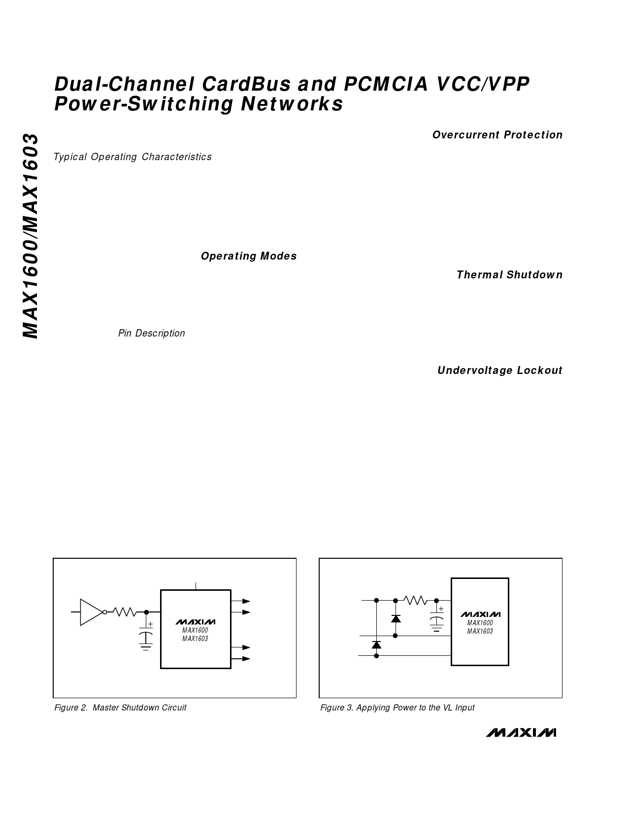
Driving the VL pin low with an external logic gate (master
shutdown) reduces total supply current to1µA (Figure 2).
Operating Modes
The MAX1600/MAX1603 are compatible with the Cirrus
CL-PD67XX, Databook DB86184, and Intel 82365SL PC
Card Interface Controllers (PCIC). Eight control inputs
select the internal switches’ positions and the operating
modes according to the input code. Select the proper
code format for the chosen controller with the CODE
input pin (see Pin Description and Tables 1, 2, and 3).
CODE reconfigures the logic decoder to one of three
interface controllers:
Low = Standard “Intel” code (Figure 5)
High = “Cirrus” code (Figure 4)
Midsupply = “Databook” code (Figure 6)
An additional 1µA (3µA max) of VL supply current will
flow if CODE = midsupply (VL / 2).
The MAX1600/MAX1603 have three operating modes:
normal, standby, and shutdown. Normal mode supplies
the selected outputs with their appropriate supply volt-
ages. Standby mode places all switches at ground,
high impedance, or a combination of the two. Shutdown
mode turns all switches off, and puts the VCC and VPP
outputs into a high-impedance state. Pull VL low to
enter shutdown mode. To ensure a 0.05V/µs fall rate on
VL, use a 1kΩ series resistor and a 0.1µF capacitor to
ground (Figure 2).
Overcurrent Protection
Peak detecting circuitry protects both the VCC and VPP
switches against overcurrent conditions. When current
through any switch exceeds the internal current limit
(4A for VCC switches and 200mA for VPP switches) the
switch turns off briefly, then turns on again at the con-
trolled rise rate. If the overcurrent condition lasts more
than 2µs, the FAULT output goes low. FAULT is not
latched. A continuous short-circuit condition results in a
pulsed output current and a pulsed FAULT output until
thermal shutdown is reached. FAULT is open-drain and
requires an external pull-up resistor.
Thermal Shutdown
If the IC junction temperature rises above +150°C, the
thermal shutdown circuitry opens all switches, including
the GND switches, and FAULT is pulled low. When the
temperature falls below +130°C, the switches turn on
again at the controlled rise rate. If the overcurrent con-
dition remains, the part cycles between thermal shut-
down and overcurrent.
Undervoltage Lockout
If the VX or VY switch input voltage drops below 1.5V,
the associated switch turns off and FAULT goes low.
For example, if VY is 3.3V and VX is 0V, and if the inter-
face controller selects VY, the VCCA output will be
3.3V. If VX is selected, VCCA changes to a high-imped-
ance output and FAULT goes low.
When a voltage is initially applied to 12IN_, it must be
greater than 8V to allow the switch to operate.
Operation continues until the voltage falls below 2V (the
VPP output is high impedance).
When VL drops to less than 2.3V, all switches are
turned off and the VCC and VPP outputs are high
impedance.
3.3V
1k
VY VPPA
VL
VCCA
TO
74HC04 0.1µF
MAX1600
MAX1603
SOCKETS
A AND B
+5V
VPPB
VCCB
VL
MAX1600
VX MAX1603
VY
Figure 2. Master Shutdown Circuit
Figure 3. Applying Power to the VL Input
10 ______________________________________________________________________________________
Share Link: 