MAX3349E 查看數據表(PDF) - Maxim Integrated
零件编号
产品描述 (功能)
生产厂家
MAX3349E Datasheet PDF : 16 Pages
| |||
Hi-Speed USB 2.0 Full-Speed Transceiver
with UART Multiplexing Mode
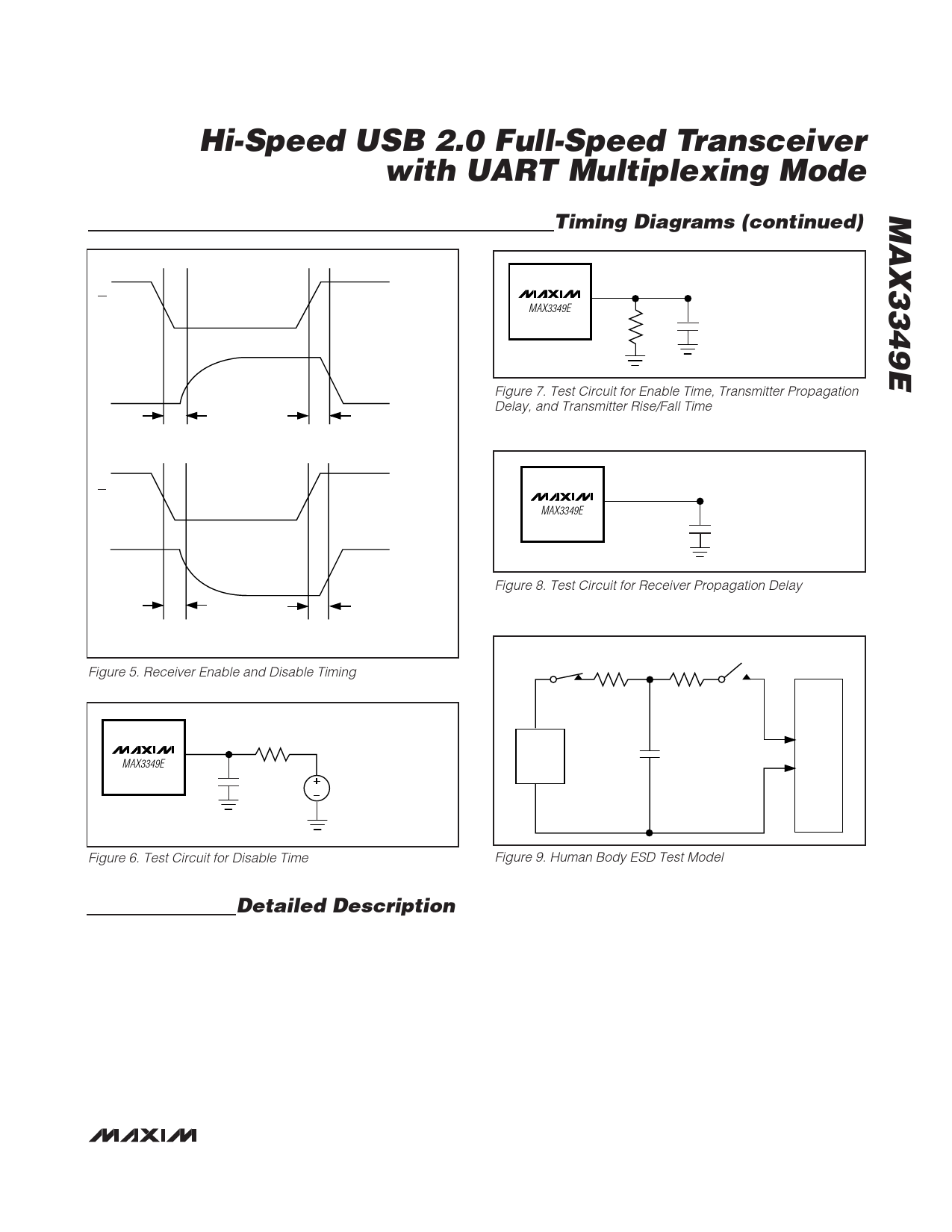
Timing Diagrams (continued)
OE
VP/VM
tPLZ_SE
OE
VP/VM
D+/D- CONNECTED TO GND,
VP/VM CONNECTED
TO PULLUP
tPZL_SE
D+/D- CONNECTED TO +3V,
VP/VM CONNECTED
TO PULLDOWN
tPHZ_SE
tPZH_SE
Figure 5. Receiver Enable and Disable Timing
MAX3349E
TEST
POINT 220Ω
D+/D-
CL
50pF
1. DISABLE TIME (D+/D-)
MEASUREMENT
V = 0 FOR tPHZ
V = VTRM FOR tPLZ
MAX3349E
D+/D-
TEST
POINT
1. ENABLE TIME (D+/D-)
MEASUREMENT
15kΩ
2. VP/VM TO D+/D-
CL
PROPAGATION DELAY
50pF 3. D+/D- RISE/FALL TIMES
Figure 7. Test Circuit for Enable Time, Transmitter Propagation
Delay, and Transmitter Rise/Fall Time
MAX3349E RCV/VP/VM
TEST
POINT
1. D+/D- TO RCV/VM/VP
PROPAGATION DELAYS
CL
15pF
Figure 8. Test Circuit for Receiver Propagation Delay
RC
RD
1MΩ
1.5kΩ
CHARGE-CURRENT-
LIMIT RESISTOR
DISCHARGE
RESISTANCE
HIGH-
VOLTAGE
DC
SOURCE
Cs
100pF
STORAGE
CAPACITOR
DEVICE
UNDER
TEST
Figure 6. Test Circuit for Disable Time
Figure 9. Human Body ESD Test Model
Detailed Description
The MAX3349E ±15kV ESD-protected, USB transceiver pro-
vides a full-speed USB interface to a microprocessor or
ASIC. The device supports enumeration, suspend, and
VBUS detection. A special UART multiplexing mode routes
external UART signals (Rx and Tx) to D+ and D-, allowing
the use of a shared connector to reduce cost and part count
for mobile devices.
The UART interface allows mobile devices such as PDAs,
cellular phones, and digital cameras to use either UART or
USB signaling through the same connector. The MAX3349E
features a separate UART voltage supply input. The
MAX3349E supports a maximum UART baud rate of
921kbaud.
Upon connection to a USB host, the MAX3349E enters
USB mode and provides a full-speed USB 2.0-compli-
ant interface through VP, VM, RCV, and OE. The
MAX3349E features internal series resistors on D+ and
D-, and an internal 1.5kΩ pullup resistor to D+ to allow
the device to logically connect and disconnect from the
USB bus while plugged in. A suspend mode is provid-
ed for low-power operation. D+ and D- are protected
from electrostatic discharge (ESD) up to ±15kV. To
ensure full ±15kV ESD protection, bypass VBUS to GND
_______________________________________________________________________________________ 9
Share Link: 