MAX4411BEBE-T 查看數據表(PDF) - Maxim Integrated
零件编号
产品描述 (功能)
生产厂家
MAX4411BEBE-T
Maxim Integrated

MAX4411BEBE-T Datasheet PDF : 18 Pages
| |||
80mW, Fixed-Gain, DirectDrive, Stereo
Headphone Amplifier with Shutdown
MICROPHONE
AMPLIFIER
OUTPUT
AUDIO
INPUT
MICROPHONE
AMPLIFIER
MICROPHONE
BIAS
AUDIO
INPUT
MAX4411
HEADPHONE DRIVER
Figure 2. Earbud Speaker/Microphone Combination Headset
Configuration
method raises some issues:
• The sleeve is typically grounded to the chassis.
Using this biasing approach, the sleeve must be
isolated from system ground, complicating product
design.
• During an ESD strike, the driver’s ESD structures
are the only path to system ground. Thus, the driver
must be able to withstand the full ESD strike.
• When using the headphone jack as a line out to other
equipment, the bias voltage on the sleeve may con-
flict with the ground potential from other equipment,
resulting in possible damage to the drivers.
• When using a combination microphone and speaker
headset, the microphone typically requires a GND
reference. The driver DC bias on the sleeve conflicts
with the microphone requirements (Figure 2).
Low-Frequency Response
In addition to the cost and size disadvantages of the DC-
blocking capacitors required by conventional head-
phone amplifiers, these capacitors limit the amplifier’s
low-frequency response and can distort the audio signal:
1) The impedance of the headphone load and the DC-
blocking capacitor forms a highpass filter with the
-3dB point set by:
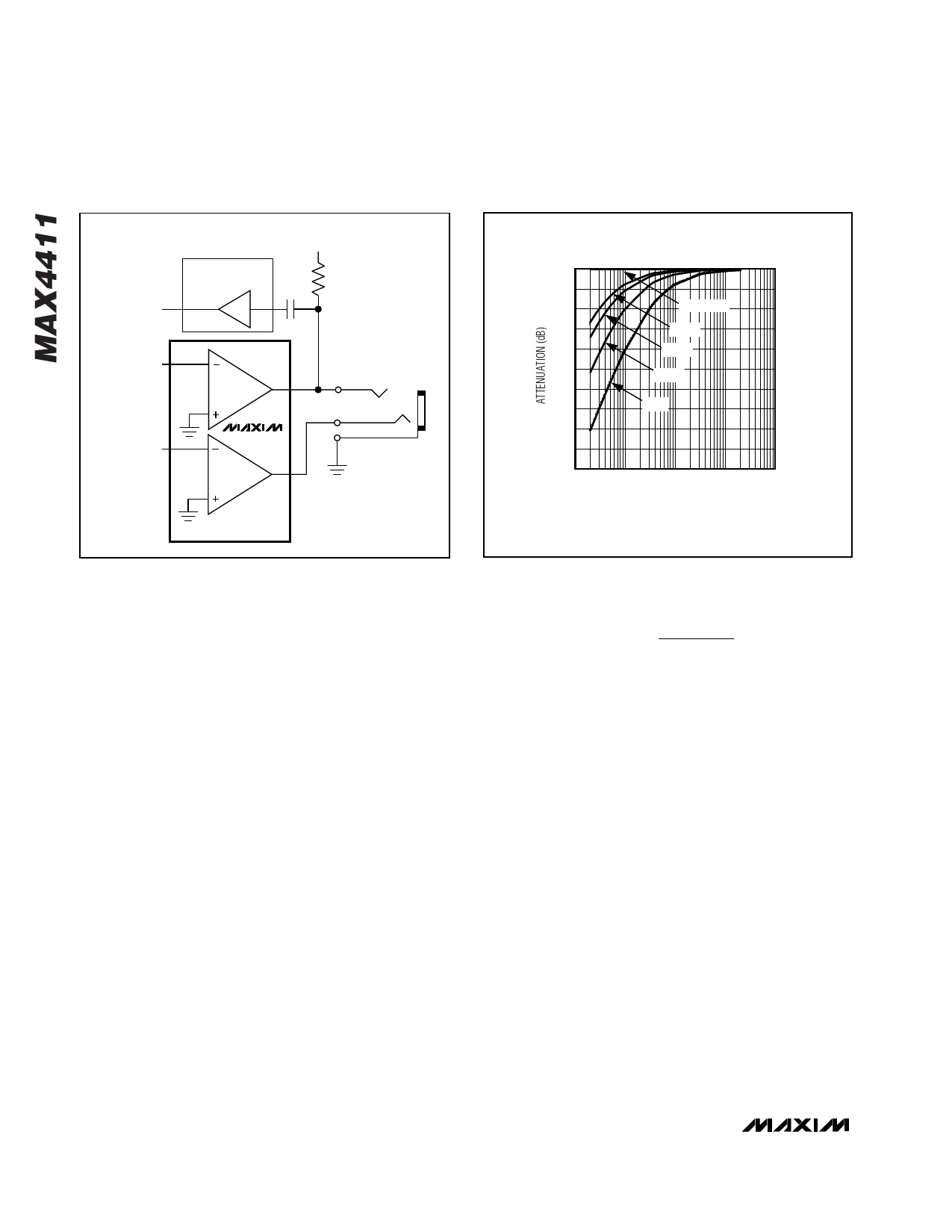
0
-3
-6
-9
-12
-15
-18
-21
-24
-27
-30
10
LOW-FREQUENCY ROLLOFF
(RL = 16Ω)
DirectDrive
330µF
220µF
100µF
33µF
100
1k
10k
100k
FREQUENCY (Hz)
Figure 3. Low-Frequency Attenuation for Common DC-Blocking
Capacitor Values
f−3dB
=
1
2πRLCOUT
where RL is the impedance of the headphone and
COUT is the value of the DC-blocking capacitor.
The highpass filter is required by conventional sin-
gle-ended, single power-supply headphone drivers
to block the midrail DC-bias component of the audio
signal from the headphones. The drawback to the
filter is that it can attenuate low-frequency signals.
Larger values of COUT reduce this effect but result
in physically larger, more expensive capacitors.
Figure 3 shows the relationship between the size of
COUT and the resulting low-frequency attenuation.
Note that the -3dB point for a 16Ω headphone with a
100µF blocking capacitor is 100Hz, well within the nor-
mal audio band, resulting in low-frequency attenuation
of the reproduced signal.
2) The voltage coefficient of the DC-blocking capacitor
contributes distortion to the reproduced audio signal
as the capacitance value varies as the function of
the voltage across the capacitor changes. At low
frequencies, the reactance of the capacitor domi-
nates at frequencies below the -3dB point and the
voltage coefficient appears as frequency-depen-
dent distortion. Figure 4 shows the THD+N intro-
10 ______________________________________________________________________________________
Share Link: