MAX639(1997) 查看數據表(PDF) - Maxim Integrated
零件编号
产品描述 (功能)
生产厂家
MAX639
(Rev.:1997)
(Rev.:1997)
Maxim Integrated

MAX639 Datasheet PDF : 12 Pages
| |||
5V/3.3V/3V/Adjustable, High-Efficiency,
Low IQ, Step-Down DC-DC Converters
______________________________________________________________Pin Description
PIN
NAME
FUNCTION
1
VOUT
Sense Input for regulated-output operation. Internally connected to an on-chip voltage divider and to
the variable duty-cycle, on-demand oscillator. It must be connected to the external regulated output.
2
LBO
Low-Battery Output. An open-drain N-channel MOSFET sinks current when the voltage at LBI drops
below 1.28V.
3
LBI
Low-Battery Input. When the voltage at LBI drops below 1.28V, LBO sinks current.
4
GND
Ground
5
LX
Drain of a PMOS power switch that has its source connected to V+. LX drives the external inductor,
which provides current to the load.
6
V+
Positive Supply-Voltage Input. Should not exceed 11.5V
Dual-Mode Feedback Pin. When VFB is grounded, the internal voltage divider sets the output to 5V
7
VFB
(MAX639), 3.3V (MAX640) or 3V (MAX653). For adjustable operation, connect VFB to an external volt-
age divider.
Shutdown Input — active low. When pulled below 0.8V, the LX power switch stays off, shutting down
8
SHDN
the regulator. When the shutdown input is above 2V, the regulator stays on. Tie SHDN to V+ if shut-
down mode is not used.
____________________Getting Started
Designing power supplies with the MAX639/MAX640/
MAX653 is easy. The few required external components
are readily available. The most general applications use
the following components:
(1) Capacitors: For the input and output filter capaci-
tors, try using electrolytics in the 100µF range, or
use low-ESR capacitors to minimize output ripple.
Capacitor values are not critical.
(2) Diode: Use the popular 1N5817 or equivalent
Schottky diode.
(3) Inductor: For the highest output current, choose a
100µH inductor with an incremental saturation cur-
rent rating of at least 600mA. To obtain the highest
efficiencies and smallest size, refer to the Inductor
Selection section.
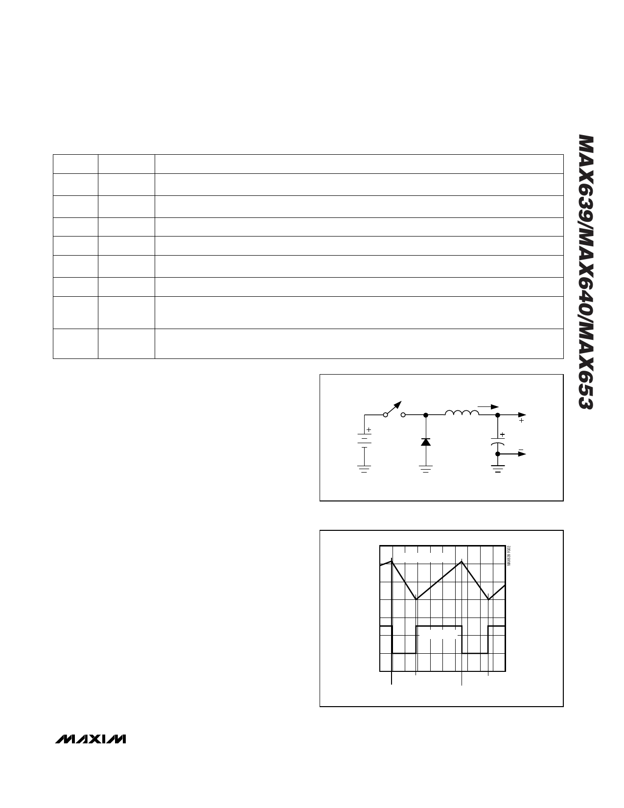
_______________Detailed Description
Figure 1 shows a simplified, step-down DC-DC con-
verter. When the switch is closed, a voltage equal to
(V+ - VOUT) is applied to the inductor. The current
through the inductor ramps up, storing energy in the
inductor’s magnetic field. This same current also flows
into the output filter capacitor and load. When the switch
opens, the current continues to flow through the inductor
in the same direction, but must also flow through the
diode. The inductor alone supplies current to the load
when the switch is open. This current decays to zero as
the energy stored in the inductor’s magnetic field is
transferred to the output filter capacitor and the load.
L
IL
VL
V+
COUT
VOUT
Figure 1. Simplified Step-Down Converter
IL AT 200mA/div
0A
0V
VL AT 5V/div
SWITCH ON
SWITCH OFF
SWITCH ON
SWITCH OFF
Figure 2. Simplified Step-Down Converter Operation
_______________________________________________________________________________________ 7
Share Link: