MAX690A(1993) 查看數據表(PDF) - Maxim Integrated
零件编号
产品描述 (功能)
生产厂家
MAX690A Datasheet PDF : 12 Pages
| |||
Microprocessor Supervisory Circuits
connected directly to the VBATT input of the
MAX690A/MAX692A/MAX802L/MAX802M/MAX805L with
no additional circuitry (see the Typical Operating Circuit).
However, batteries with open-circuit voltages that are
greater cannot be used for backup, as current is sourced
into the substrate through the diode (D1 in Figure 3) when
VCC is close to the reset threshold.
Operation
Without a Backup Power Source
If a backup power source is not used, ground VBATT
and connect VOUT to VCC. Since there is no need to
switch over to any backup power source, VOUT does
not need to be switched. A direct connection to VCC
eliminates any voltage drops across the switch which
may push VOUT below VCC.
Replacing the Backup Battery
The backup battery can be removed while VCC remains
valid, without danger of triggering RESET/RESET. As
long as VCC stays above the reset threshold, battery-
backup mode cannot be entered. In other switchover
+5V
R1
VCC
PFI
MAX690A
MAX692A
PFO
MAX802L
MAX802M
R2
MAX805L
GND
V-
+5V
PFO
0V
VTRIP
0V
V-
ICs where battery-backup mode is entered whenever
VBATT gets close to VCC, an unconnected VBATT pin
accumulates leakage charge and triggers
RESET/RESET in error.
Adding Hysteresis to the
Power-Fail Comparator
Hysteresis adds a noise margin to the power-fail com-
parator and prevents repeated triggering of PFO when
VIN is close to its trip point. Figure 6 shows how to add
hysteresis to the power-fail comparator. Select the
ratio of R1 and R2 such that PFI sees 1.25V when VIN
falls to its trip point (VTRIP). R3 adds the hysteresis. It
will typically be an order of magnitude greater than R1
or R2 (about 10 times either R1 or R2). The current
through R1 and R2 should be at least 1µA to ensure
that the 25nA (max) PFI input current does not shift the
trip point. R3 should be larger than 10kΩ so it does not
load down the PFO pin. Capacitor C1 adds additional
noise rejection.
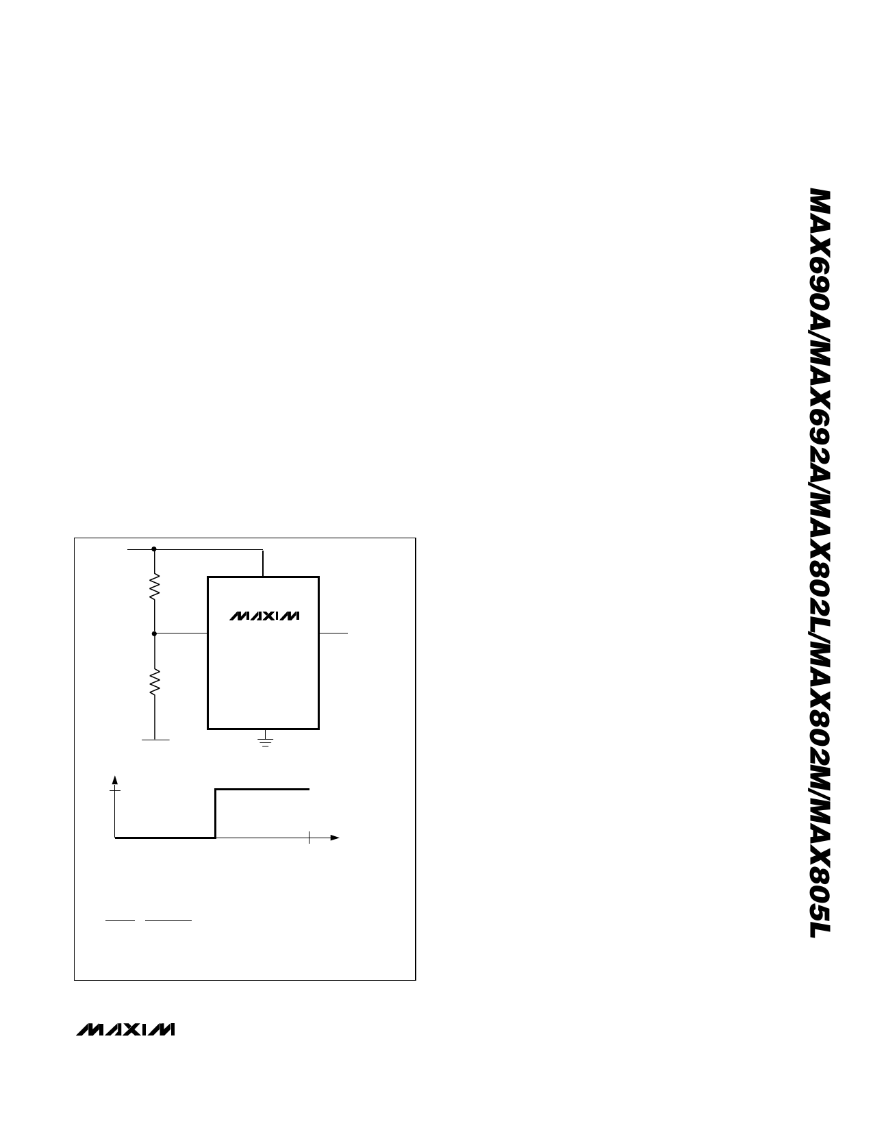
Monitoring a Negative Voltage
The power-fail comparator can be used to monitor a
negative supply rail using the circuit of Figure 7. When
the negative rail is good (a negative voltage of large
magnitude), PFO is low. When the negative rail is
degraded (a negative voltage of lesser magnitude),
PFO goes high. This circuit’s accuracy is affected by
the PFI threshold tolerance, the VCC line, and the resis-
tors.
Interfacing to µPs with
Bidirectional Reset Pins
µPs with bidirectional reset pins, such as the Motorola
68HC11 series, can contend with the
MAX690A/MAX692A/MAX802L/MAX802M RESET out-
put. If, for example, the RESET output is driven high
and the µP wants to pull it low, indeterminate logic lev-
els may result. To correct this, connect a 4.7kΩ resis-
tor between the RESET output and the µP reset I/O, as
in Figure 8. Buffer the RESET output to other system
components
NOT5 E−R:11.2V5TR=IP1I.S25N-ERG2VATRTIIVPE
Figure 7. Monitoring a Negative Voltage
_______________________________________________________________________________________ 9
Share Link: 