MAX817_CSA 查看數據表(PDF) - Maxim Integrated
零件编号
产品描述 (功能)
生产厂家
MAX817_CSA Datasheet PDF : 16 Pages
| |||
+5V Microprocessor Supervisory Circuits
Any time a reset is generated, the CE transmission gate
remains disabled and CE IN remains high impedance
(regardless of CE IN activity) for the reset timeout peri-
od. When the CE transmission gate is enabled, the
impedance of CE IN appears as a 40Ω resistor in series
with the load at CE OUT. The propagation delay
through the CE transmission gate depends on VCC, the
source impedance of the drive connected to CE IN,
and the loading on CE OUT (see Typical Operating
Characteristics). The CE propagation delay is produc-
tion tested from the 50% point on CE IN to the 50%
point on CE OUT using a 50Ω driver and a 50pF load
capacitance (Figure 7). For minimum propagation
delay, minimize the capacitive load at CE OUT and use
a low-output-impedance driver.
Chip-Enable Output (MAX818)
When the CE transmission gate is enabled, the imped-
ance of CE OUT is equivalent to a 40Ω resistor in series
with the source driving CE IN. In the disabled mode,
the transmission gate is off and an active pull-up con-
nects CE OUT to OUT (Figure 5). This pull-up turns off
when the transmission gate is enabled.
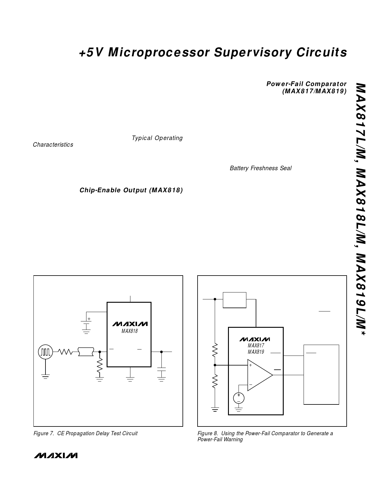
Power-Fail Comparator
(MAX817/MAX819)
The MAX817/MAX819 PFI input is compared to an inter-
nal reference. If PFI is less than the power-fail threshold
(VPFT), PFO goes low. The power-fail comparator is
intended for use as an undervoltage detector to signal a
failing power supply (Figure 8). However, the comparator
does not need to be dedicated to this function because it
is completely separate from the rest of the circuitry.
The power-fail comparator turns off and PFO goes low
when VCC falls below VBATT. During the reset timeout
period (tRP), PFO is forced high, regardless of the state
of VPFI (see Battery Freshness Seal section). If the com-
parator is unused, connect PFI to ground and leave PFO
unconnected. PFO can be connected to MR on the
MAX819 so that a low voltage on PFI will generate a
reset (Figure 9). In this configuration, when the monitored
voltage causes PFI to fall below VPFT, PFO pulls MR low,
causing a reset to be asserted. Reset remains asserted
as long as PFO holds MR low, and for tRP (200ms) after
PFO pulls MR high when the monitored supply is above
the programmed threshold. When PFO is connected to
MR, it is not possible to enable the battery freshness
seal. Enabling the battery freshness seal requires MR to
be high or open. Once the battery freshness seal is
enabled, it is no longer affected by PFO’s connection to
MR.
+5V
VCC
BATT
MAX818
CE IN
CE OUT
50Ω
GND
50Ω
50pF
CL*
VIN
+5V
REGULATOR
POWER-FAIL-WARNING TRIP VOLTAGE
( ) VWARN = 1.25
R1 + R2
R2
R1
PFI
R2
VCC
MAX817
MAX819
RESET
PFO
RESET
NMI µP
* CL INCLUDES LOAD CAPACITANCE, STRAY CAPACITANCE,
AND SCOPE-PROBE CAPACITANCE.
1.25V
Figure 7. CE Propagation Delay Test Circuit
Figure 8. Using the Power-Fail Comparator to Generate a
Power-Fail Warning
______________________________________________________________________________________ 11
Share Link: 