MAX8568A 查看數據表(PDF) - Maxim Integrated
零件编号
产品描述 (功能)
生产厂家
MAX8568A Datasheet PDF : 17 Pages
| |||
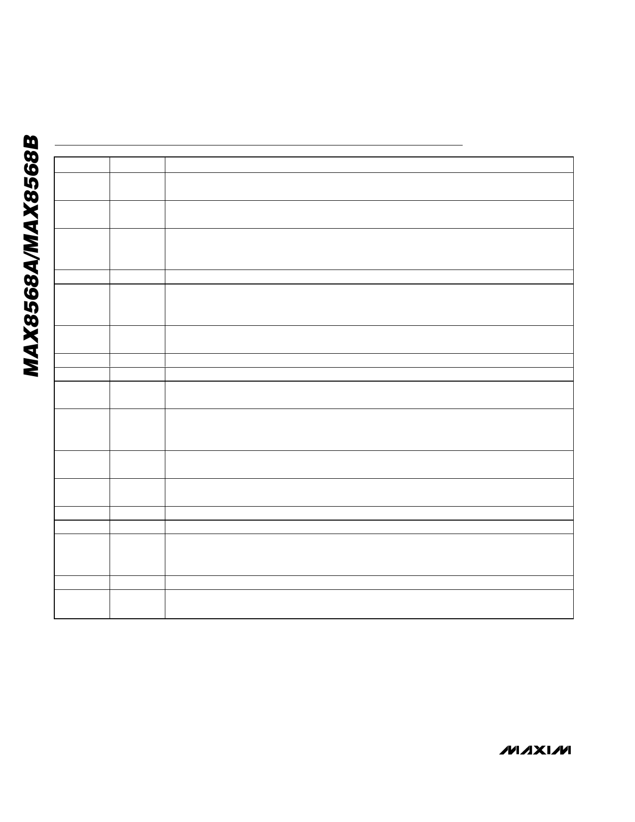
Complete Backup-Management ICs
for Lithium and NiMH Batteries
Pin Description
PIN
NAME
FUNCTION
1
IN
Main Battery Input. Connect to a 2.8V to 5.5V battery or other power source. Bypass with a 4.7µF
ceramic capacitor to GND.
2
BK
Backup Battery Input. Connect to an NiMH or rechargeable lithium backup battery. Connect a ceramic
bypass capacitor from BK to GND. See the Step-Up Capacitor Selection section for more details.
Power Ground. Connect PGND to the ground side of the BK input capacitor and BKSU output
3
PGND capacitor. Use this connection as the star point for all grounds. See the PC Board Layout and Routing
section for specific instructions regarding PGND.
4
LX
Inductor Connection for Low-IQ Step-Up DC-DC Converter
Step-Up Converter Output. Bypass with a 10µF to 22µF ceramic capacitor to PGND. The BKSU output
5
BKSU voltage is set to either 3.3V or 2.5V without resistors, or to an adjustable voltage with an external
resistor-divider. See the Setting the Step-Up Converter Voltage section.
6
LDO
2.5V (MAX8568A) or 1.8V (MAX8568B), 10mA LDO Output for Memory Supply. LDO is powered from
BKSU. Bypass with a 4.7µF ceramic capacitor to GND.
7
OD1
11Ω Open-Drain Output. OD1 drives the gate of an external pMOS switch.
8
OD2
11Ω Open-Drain Output. OD2 drives the gate of an external pMOS switch.
9
NI/LI
Selects NiMH or Rechargeable Lithium Backup Battery. Connect NI/LI to BKSU if an NiMH backup
battery is used. Connect NI/LI to GND if a rechargeable lithium backup battery is used.
Sets the BKSU Output Voltage. Connect to GND for 3.3V output at BKSU. Connect to BKSU for 2.5V
10
BKV
output. Connect to the midpoint of a resistor-divider connected from BKSU to GND for adjustable
output. See the Setting the Step-Up Converter Voltage section.
11
INOK
Main Battery Monitor. When VINOK falls below 2.43V, charging stops and backup mode starts. The
step-up converter and LDO turn on, and OD1 and OD2 go high impedance.
12
CHGI
Sets Backup Battery Charge Current. Connect a resistor from CHGI to GND to set the charge current.
See the Setting the Charge Current section for details.
13
GND Ground. Connect to the exposed paddle. Star all grounds at the BKSU output capacitor ground.
14
STRTV Sets Fast-Charge Start Voltage for NiMH. See the Using an NiMH Backup Battery section.
Sets Fast-Charge Stop Voltage for NiMH, as Well as the Battery Regulation Voltage for Both
15
TERMV Rechargeable Lithium and Maximum Voltage for NiMH. See the Using a Lithium Backup Battery
section and the Using an NiMH Backup Battery section.
16
REF
Reference Output. Bypass with a 0.22µF ceramic capacitor to GND.
EP
—
Exposed Paddle. Connect to the analog ground plane. EP also functions as a heatsink. Solder to the
circuit-board analog ground plane.
8 _______________________________________________________________________________________
Share Link: 