MAX9724A(2007) 查看數據表(PDF) - Maxim Integrated
零件编号
产品描述 (功能)
生产厂家
MAX9724A
(Rev.:2007)
(Rev.:2007)
Maxim Integrated

MAX9724A Datasheet PDF : 19 Pages
| |||
60mW, DirectDrive, Stereo Headphone Amplifier
with Low RF Susceptibility and Shutdown
ABSOLUTE MAXIMUM RATINGS
VDD to GND ..............................................................-0.3V to +6V
PVSS to SVSS .........................................................-0.3V to +0.3V
PGND to SGND .....................................................-0.3V to +0.3V
C1P to PGND..............................................-0.3V to (VDD + 0.3V)
C1N to PGND............................................(PVSS - 0.3V) to +0.3V
PVSS and SVSS to PGND..........................................-6V to +0.3V
IN_ to SGND (MAX9724A)..........................-0.3V to (VDD + 0.3V)
IN_ to SGND (MAX9724B) .............(SVSS - 0.3V) to (VDD + 0.3V)
OUT_ to SVSS (Note 1) ....-0.3V to Min (VDD - SVSS + 0.3V, +9V)
OUT_ to VDD (Note 2) ......+0.3V to Max (SVSS - VDD - 0.3V, -9V)
SHDN to _GND.........................................................-0.3V to +6V
OUT_ Short Circuit to GND ........................................Continuous
Short Circuit between OUTL and OUTR ....................Continuous
Continuous Input Current into PVSS..................................260mA
Continuous Input Current (any other pin) .........................±20mA
Continuous Power Dissipation (TA = +70°C)
12-Bump USCP (derate 6.5mW/°C above +70°C) ........519mW
12-Pin TQFN (derate 14.7mW/°C above +70°C) .........1177mW
Operating Temperature Range ...........................-40°C to +85°C
Storage Temperature Range .............................-65°C to +150°C
Junction Temperature ......................................................+150°C
Lead Temperature (soldering, 10s) .................................+300°C
Bump Temperature (soldering) Reflow............................+235°C
Note 1: OUTR and OUTL should be limited to no more than 9V above SVSS, or above VDD + 0.3V, whichever limits first.
Note 2: OUTR and OUTL should be limited to no more than 9V below VDD, or below SVSS - 0.3V, whichever limits first.
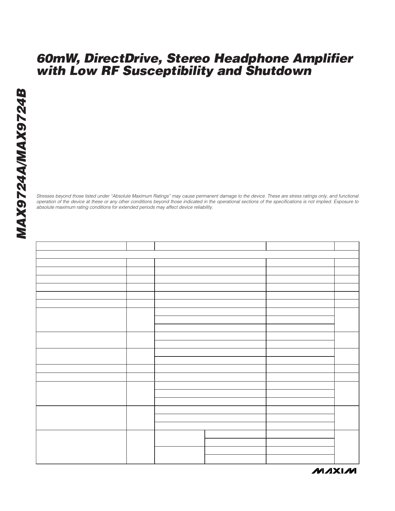
Stresses beyond those listed under “Absolute Maximum Ratings” may cause permanent damage to the device. These are stress ratings only, and functional
operation of the device at these or any other conditions beyond those indicated in the operational sections of the specifications is not implied. Exposure to
absolute maximum rating conditions for extended periods may affect device reliability.
ELECTRICAL CHARACTERISTICS
(VDD = 5V, PGND = SGND, SHDN = 5V, C1 = C2 = 1µF, RL = ∞, resistive load reference to ground; for MAX9724A gain = -1.5V/V
(RIN = 20kΩ, RF = 30kΩ); for MAX9724B gain = -1.5V/V (internally set), TA = -40°C to +85°C, unless otherwise noted. Typical values
are at TA = +25°C, unless otherwise noted.) (Note 3)
PARAMETER
GENERAL
Supply Voltage Range
Quiescent Current
Shutdown Current
Shutdown to Full Operation
Input Impedance
Output Offset Voltage
Power-Supply Rejection Ratio
Output Power (TQFN)
Output Power (UCSP)
Voltage Gain
Channel-to-Channel Gain
Tracking
Total Harmonic Distortion Plus
Noise (Note 6)
SYMBOL
CONDITIONS
VDD
ICC
ISHDN
tSON
RIN
VOS
PSRR
POUT
POUT
AV
Guaranteed by PSRR test
SHDN = SGND = PGND
MAX9724B, measured at IN_
(Note 4)
VDD = 2.7V to 5.5V, TA = +25°C
f = 1kHz, 100mVP-P (Note 4)
f = 20kHz, 100mVP-P (Note 4)
RL = 32Ω, THD+N = 1%
RL = 16Ω, THD+N = 1%
RL = 32Ω, THD+N = 1%
RL = 16Ω, THD+N = 1%
MAX9724B (Note 5)
MAX9724B
THD+N
RL = 1kΩ, VOUT = 2VRMS, fIN = 1kHz
RL = 32Ω, POUT = 50mW, fIN = 1kHz
RL = 16Ω, POUT = 35mW, fIN = 1kHz
MIN TYP MAX UNITS
2.7
5.5
V
3.5
5.5
mA
0.1
1
µA
180
µs
12
19
28
kΩ
±1.5 ±10
mV
69
86
80
dB
65
30
63
mW
42
25
45
mW
35
-1.52 -1.5 -1.48 V/V
±0.15
%
0.003
0.02
%
0.04
2 _______________________________________________________________________________________
Share Link: