MAX9724A(2007) 查看數據表(PDF) - Maxim Integrated
零件编号
产品描述 (功能)
生产厂家
MAX9724A
(Rev.:2007)
(Rev.:2007)
Maxim Integrated

MAX9724A Datasheet PDF : 19 Pages
| |||
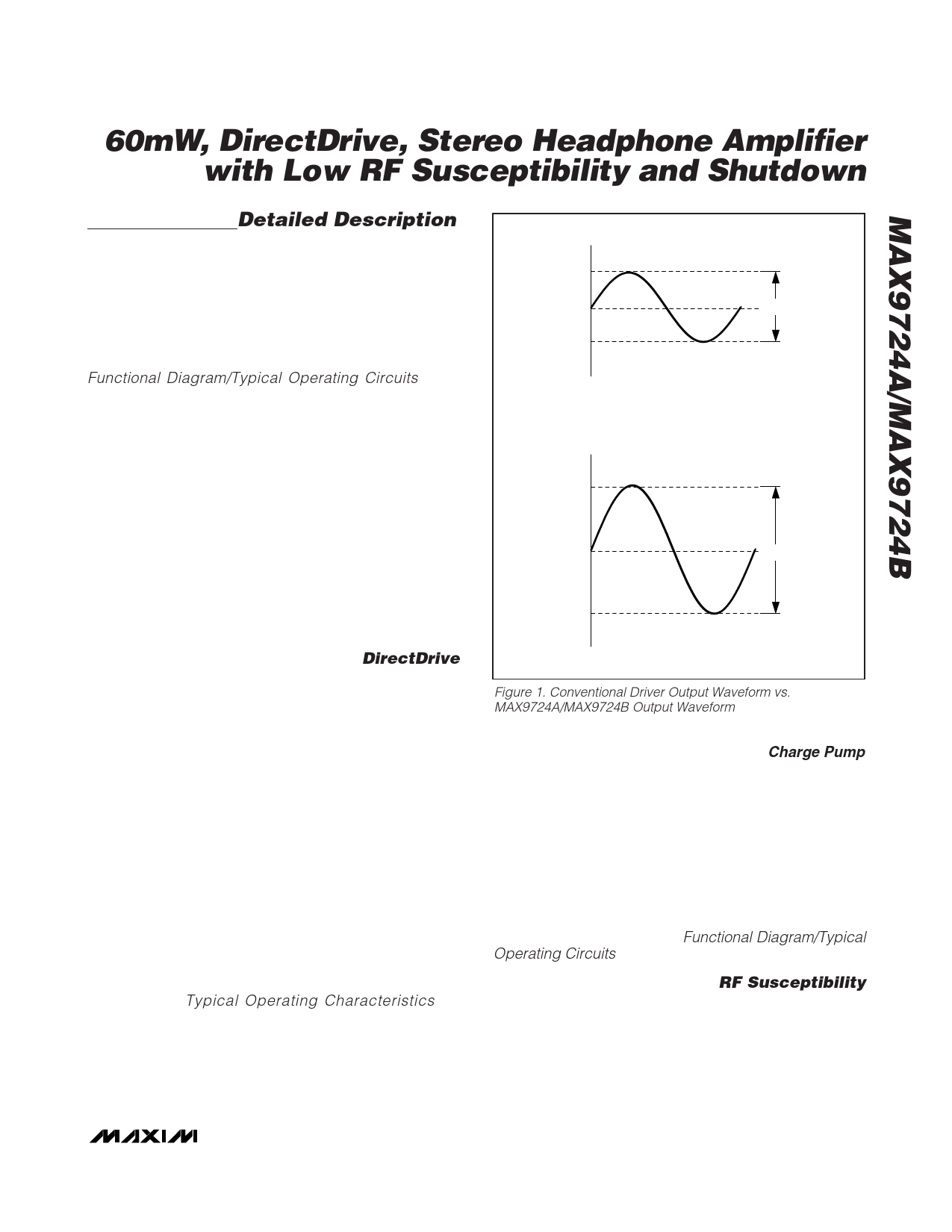
60mW, DirectDrive, Stereo Headphone Amplifier
with Low RF Susceptibility and Shutdown
where TJ(MAX) is +150°C, TA is the ambient tempera-
ture, and θJA is the reciprocal of the derating factor in
°C/W as specified in the Absolute Maximum Ratings
section. For example, θJA of the thin QFN package is
+68°C/W, and 154.2°C/W for the UCSP package.
The MAX9724A/MAX9724B have two power dissipation
sources; a charge pump and the two output amplifiers.
If power dissipation for a given application exceeds the
maximum allowed for a particular package, reduce
VDD, increase load impedance, decrease the ambient
temperature, or add heatsinking to the device. Large
output, supply, and ground traces decrease θJA, allow-
ing more heat to be transferred from the package to the
surrounding air.
Thermal-overload protection limits total power dissipa-
tion in the MAX9724A/MAX9724B. When the junction
temperature exceeds +150°C, the thermal protection
circuitry disables the amplifier output stage. The ampli-
fiers are enabled once the junction temperature cools
by approximately 12°C. This results in a pulsing output
under continuous thermal-overload conditions.
Output Dynamic Range
Dynamic range is the difference between the noise floor
of the system and the output level at 1% THD+N.
Determine the system’s dynamic range before setting the
maximum output gain. Output clipping occurs if the out-
put signal is greater than the dynamic range of the sys-
tem. The DirectDrive architecture of the MAX9724A/
MAX9724B has increased the dynamic range compared
to other single-supply amplifiers.
Maximum Output Swing
VDD < 4.35V
If the output load impedance is greater than 1kΩ, the
MAX9724A/MAX9724B can swing within a few millivolts
of their supply rail. For example, with a 3.3V supply, the
output swing is 2VRMS, or 2.83V peak while maintaining
a low 0.003% THD+N. If the supply voltage drops to
3V, the same 2.83V peak has only 0.05% THD+N.
VDD > 4.35V
Internal device structures limit the maximum voltage
swing of the MAX9724A/MAX9724B when operated at
supply voltages greater than 4.35V. The output must not
be driven such that the peak output voltage exceeds the
opposite supply voltage by 9V. For example, if VDD =
5V, the charge pump sets PVSS = -5V. Therefore, the
peak output swing must be less than ±4V to prevent
exceeding the absolute maximum ratings.
UVLO
The MAX9724A/MAX9724B feature an undervoltage
lockout (UVLO) function that prevents the device from
operating if the supply voltage is less than 2.7V. This fea-
ture ensures proper operation during brownout condi-
tions and prevents deep battery discharge. Once the
supply voltage exceeds the UVLO threshold, the
MAX9724A/MAX9724B charge pump is turned on and
the amplifiers are powered, provided that SHDN is high.
Component Selection
Input-Coupling Capacitor
The input capacitor (CIN), in conjunction with the input
resistor (RIN), forms a highpass filter that removes the
DC bias from an incoming signal (see the Functional
Diagram/Typical Operating Circuits). The AC-coupling
capacitor allows the device to bias the signal to an opti-
mum DC level. Assuming zero-source impedance, the -
3dB point of the highpass filter is given by:
f−3dB
=
1
2πRINCIN
Choose the CIN such that f-3dB is well below the lowest
frequency of interest. Setting f-3dB too high affects the
device’s low-frequency response. Use capacitors
whose dielectrics have low-voltage coefficients, such
as tantalum or aluminum electrolytic. Capacitors with
high-voltage coefficients, such as ceramics, can result
in increased distortion at low frequencies.
Charge-Pump Capacitor Selection
Use ceramic capacitors with a low ESR for optimum
performance. For optimal performance over the extend-
ed temperature range, select capacitors with an X7R
dielectric. Table 2 lists suggested manufacturers.
Table 2. Suggested Capacitor Manufacturers
SUPPLIER
Taiyo Yuden
TDK
Murata
PHONE
800-348-2496
847-803-6100
770-436-1300
FAX
847-925-0899
847-390-4405
770-436-3030
WEBSITE
www.t-yuden.com
www.component.tdk.com
www.murata.com
_______________________________________________________________________________________ 9
Share Link: