33981 查看數據表(PDF) - Motorola => Freescale
零件编号
产品描述 (功能)
生产厂家
33981
Motorola => Freescale

33981 Datasheet PDF : 24 Pages
| |||
Freescale Semiconductor, Inc.
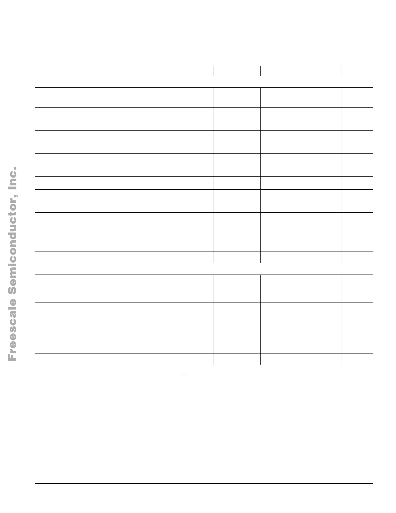
MAXIMUM RATINGS
All voltages are with respect to ground unless otherwise noted.
Rating
Symbol
Value
Unit
ELECTRICAL RATINGS
Power Supply Voltage
Steady-State
VPWR
V
-16 to 41
Input/Output Terminals Voltage (Note 1)
Output Voltage
Continuous Output Current (Note 2)
CSNS Input Clamp Current
SR Voltage
Temperature Feedback Voltage
CBOOT Voltage
VIN
VOUT
IOUT
ICSNS
VSR
VTEMP
CBOOT
-0.3 to 7.0
V
-5.0 to 41
V
40
A
10
mA
-0.3 to 54
V
-0.3 to 5.0
V
-0.3 to 54
V
OCLS Voltage
Low-Side Gate Voltage
Low-Side Drain Voltage
ESD Voltage
Human Body Model (Note 3)
Machine Model (Note 4)
VOCLS
VGLS
VDLS
VESD1
VESD2
-0.3 to 7.0
V
-0.3 to 15
V
-5.0 to 41
V
V
± 2000
± 200
Output Clamp Energy (Note 5)
ECL
TBD
J
THERMAL RATINGS
Operating Temperature
Ambient
Junction
Storage Temperature
Thermal Resistance (Note 6)
Junction to Power Die Case
Junction to Ambient
TA
TJ
TSTG
RθJC
RθJA
-40 to 125
-40 to 150
-55 to 150
1.0
20
°C
°C
°C/W
Peak Terminal Reflow Temperature During Solder Mounting (Note 7)
TSOLDER
240
°C
Power Dissipation (TA = 25°C) (Note 8)
PD
TBD
W
Notes
1. Exceeding voltage limits on INHS, INLS, CONF, CSNS, FS, TEMP, and EN terminals may cause a malfunction or permanent damage to the
device.
2. Continuous high-side output rating as long as maximum junction temperature is not exceeded. Calculation of maximum output current using
package thermal resistance is required.
3. ESD1 testing is performed in accordance with the Human Body Model (CZAP = 100 pF, RZAP = 1500 Ω).
4. ESD2 testing is performed in accordance with the Machine Model (CZAP = 200 pF, RZAP = 0 Ω) and in accordance with the system module
specification with a capacitor > 0.01 µF connected from OUT to GND.
5. Active clamp energy using single-pulse method (L = 16 mH, RL = 0, VPWR = 12 V, TJ = 150°C).
6. Device mounted on a 2s2p test board per JEDEC JESD51-2.
7. Terminal soldering temperature limit is for 10 seconds maximum duration. Not designed for immersion soldering. Exceeding these limits may
cause malfunction or permanent damage to the device.
8. Maximum power dissipation at indicated ambient temperature in free air with no heatsink used.
MOTOROLA ANALOG INTEGRATED CIRCUIT DEVICE DATA
For More Information On This Product,
Go to: www.freescale.com
33981
5
Share Link: