M66009FP 查看數據表(PDF) - MITSUBISHI ELECTRIC
零件编号
产品描述 (功能)
生产厂家
M66009FP Datasheet PDF : 8 Pages
| |||
MITSUBISHI 〈DIGITAL ASSP〉
M66009FP
8-BIT I/O EXPANDER WITH 5-BIT ADDRESS
FUNCTION
M66009 semiconductor circuit converts data from serial to
parallel and vice versa. Address can be set freely at users’
option.
It communicates with microcomputer via 4 signals lines: EN,
CLK, DI and DO.
It has 5-bit address setting input. Connect each address input
pin to VCC or GND, then the address can be determined from
among 32 patterns. When serial data arrives from microcom-
puter, this IC compares the address in the data to the address
set with these pins. If the two addresses are the same, the
given command is executed.
To output serial input data in parallel, this IC converts the
lower 8 bits of the 16-bit serial data into parallel, and outputs
each to pins D0 to D7. The upper 8 bits are processed as
address bits and command bits.
To output parallel input data in series, this IC prefixes one ac-
knowledge bit to the 8 parallel bits which respectively refer to
the status of pins D0 to D7, and then outputs 9 bits in series.
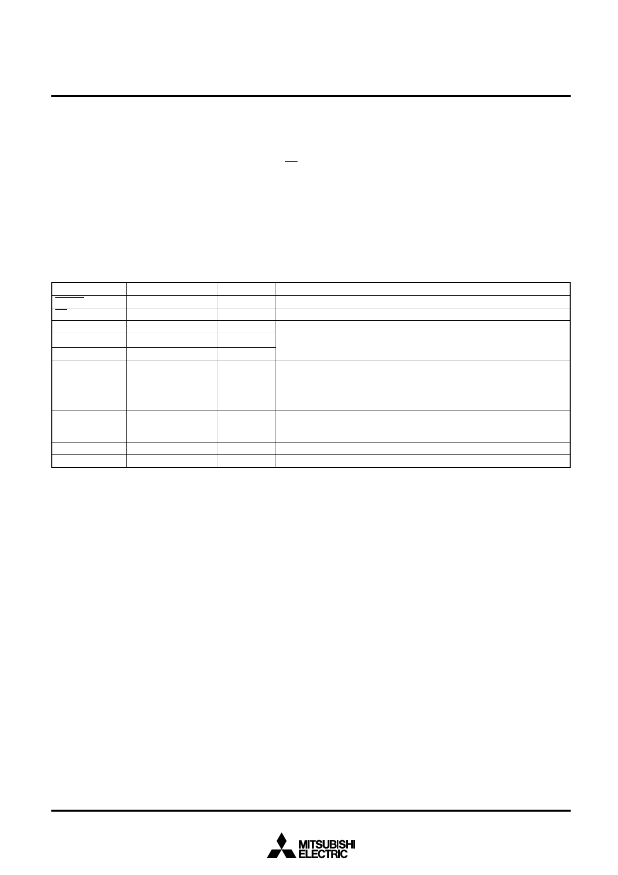
PIN DESCRIPTIONS
Pin
Name
RESET
Reset input
EN
Data enable input
CLK
Serial clock input
DI
Serial data input
DO
Serial data output
A0~A4
Address setting input
D0~D7
VCC
GND
Parallel data input/
output
Positive supply pin
Grounding pin
Input/Output
Input
Input
Input
Input
Output
Input
Input/Output
––
––
Functions
“L” level: M66009 is reset to initial state.
“L” level: M66009 becomes accessible.
Serial data that arrives at pin DI from microcomputer is taken into M66009
shift register at CLK rise edge. serial data is output from pin DO synchro-
nously with CLK fall edge.
Pin DO status stays at “H” level except during serial data output.
Connect each to Vcc or GND to set distinctive address.
Command is executed only when serial data from microcomputer includes the
same address as that set by these pins.
When connected to VCC, pin status is “1”. When connected to GND, pin status
is “0”.
Used to input/output parallel data. Because pull-down resistor is built in and
output transistor is P-ch open drain, pins in “L” output status (equals to P-ch
transistor OFF) function as input pins.
Connected positive supply (5V).
Used for grounding (0V).
INPUT/OUTPUT DATA LOGIC
Serial data input from pin DI is output in parallel from pins D0
thru D7, being inverted in logic. Parallel data input from pins
D0 thru D7 is output in series from pin DO in the same logic.
Therefore, to set I/O pins to input, DI input data should be set
to “H”.
2
Share Link: 