MCP23016 查看數據表(PDF) - Microchip Technology
零件编号
产品描述 (功能)
生产厂家
MCP23016 Datasheet PDF : 38 Pages
| |||
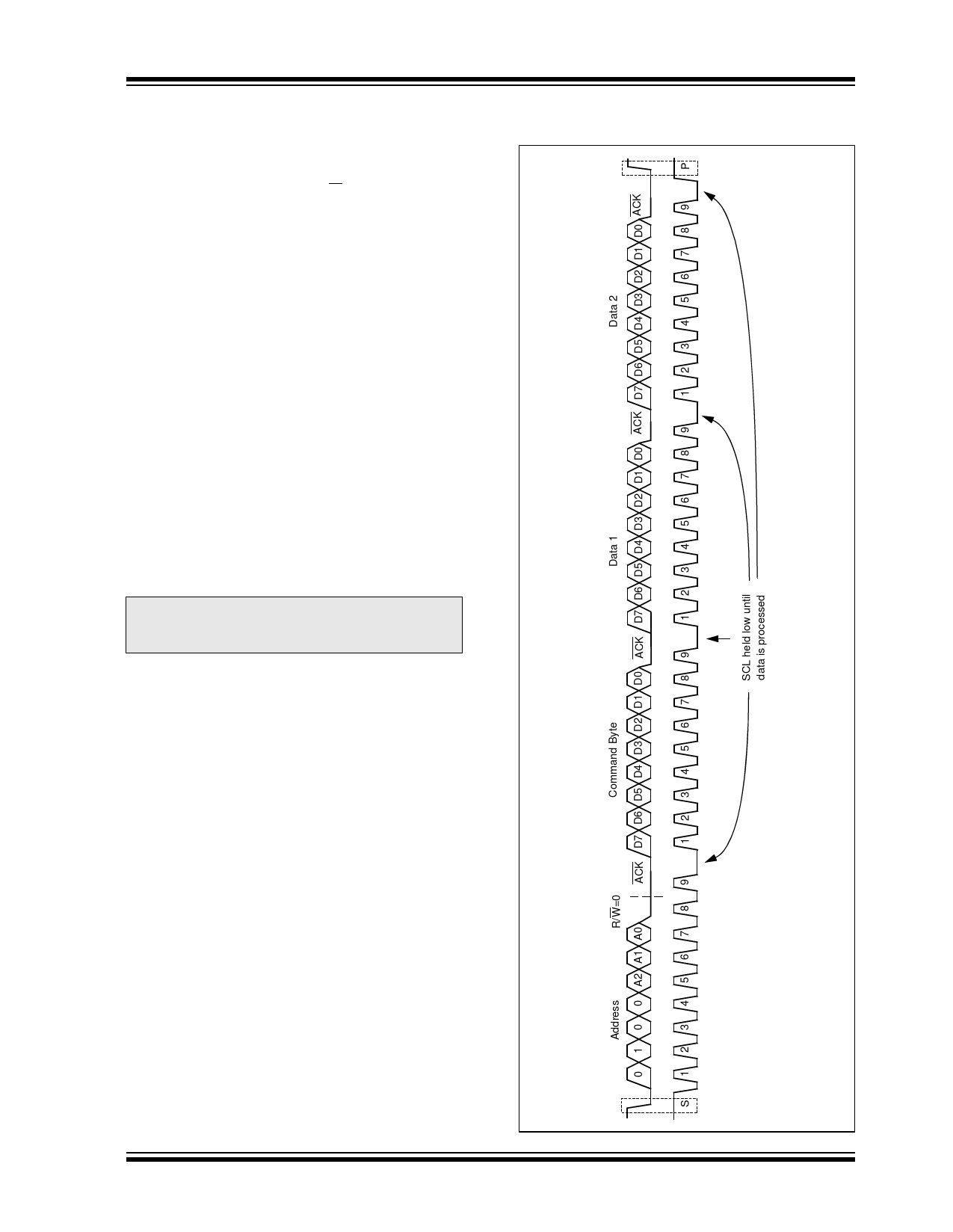
1.9.2 WRITING THE REGISTERS
To write to a MCP23016 register, the Master I2C device
needs to follow the requirements, as illustrated in
Figure 1-3. First, the device is selected by sending the
slave address and setting the R/W bit to logic ‘0’. The
command byte is sent after the address and
determines which register will be written. Table 1-3
shows the relationship of the command byte and
register.
The MCP23016 has twelve 8-bit registers. They are
configured to operate as six 16-bit register pairs,
supporting the device’s 16-bit port. These pairs are
formed based on their functions (e.g., GP0 and GP1
are grouped together). The I2C commands apply to one
register pair to provide faster access. The first data byte
following a command byte is written into the register
pointed to by the command byte, while the second data
is written into another register in the same pair. For
example, if the first byte is sent to OLAT1 (command
byte 03h), the next data byte will be written into the sec-
ond register of that pair, OLAT0. If the first byte is writ-
ten to OLAT0 (command byte 02h), the second byte
will be written to OLAT1.
There is no limitation on the number of data bytes in
one write transmission. Figure 1-4 shows the case of
multiple byte writes in one write operation. In this case,
the multiple writes are made to the same data pair.
Note:
The bus must remain free until after the
ninth clock pulse for a minimum of 12 µs
(see Table 2-5 and Figure 2-4).
MCP23016
FIGURE 1-3:
WRITE TO CONFIGURATION
REGISTERS (CASE 1)
© 2007 Microchip Technology Inc.
DS20090C-page 13
Share Link: 