MCP617 查看數據表(PDF) - Microchip Technology
零件编号
产品描述 (功能)
生产厂家
MCP617 Datasheet PDF : 38 Pages
| |||
MCP616/7/8/9
TEMPERATURE CHARACTERISTICS
Electrical Specifications: Unless otherwise indicated, VDD = +2.3V to +5.5V and VSS = GND.
Parameters
Sym Min Typ Max Units
Conditions
Temperature Ranges
Specified Temperature Range
Operating Temperature Range
Storage Temperature Range
Thermal Package Resistances
TA
-40 —
+85
TA
-40 — +125
TA
-65 — +150
°C
°C Note 1
°C
Thermal Resistance, 8L-MSOP
θJA
— 211
—
°C/W
Thermal Resistance, 8L-PDIP
θJA
— 89.3 —
°C/W
Thermal Resistance, 8L-SOIC
θJA
— 149.5 —
°C/W
Thermal Resistance, 14L-PDIP
θJA
—
70
—
°C/W
Thermal Resistance, 14L-SOIC
θJA
— 95.3 —
°C/W
Thermal Resistance, 14L-TSSOP
θJA
— 100
—
°C/W
Note 1: The MCP616/7/8/9 operate over this extended temperature range, but with reduced performance. In any case, the
Junction Temperature (TJ) must not exceed the Absolute Maximum specification of +150°C.
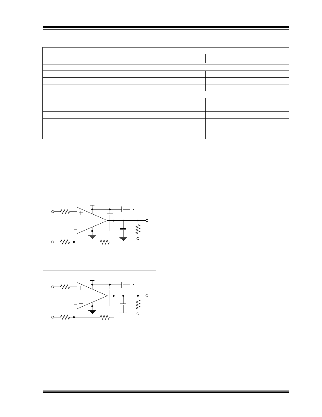
1.1 Test Circuits
The test circuits used for the DC and AC tests are
shown in Figure 1-2 and Figure 1-3. The bypass
capacitors are laid out according to the rules discussed
in Section 4.6 “Supply Bypass”.
VIN
RN
VDD/2 RG
VDD 0.1 µF 1 µF
MCP61X
RF
VOUT
CL RL
VL
FIGURE 1-2:
AC and DC Test Circuit for
Most Non-Inverting Gain Conditions.
VDD/2
RN
VIN RG
VDD 0.1 µF 1 µF
MCP61X
RF
VOUT
CL RL
VL
FIGURE 1-3:
AC and DC Test Circuit for
Most Inverting Gain Conditions.
© 2008 Microchip Technology Inc.
DS21613C-page 5
Share Link: 