MIC2779(2000) 查看數據表(PDF) - Micrel
零件编号
产品描述 (功能)
生产厂家
MIC2779 Datasheet PDF : 8 Pages
| |||
MIC2779
Applications Information
Programming the Thresholds
The low-voltage threshold is calculated using:
VBAT(lo) = VREF R1R+2R+2R+3R3
The high-voltage threshold is calculated using:
VBAT(hi)
=
VREF
R1+
R2 +
R3
R3
where, for both equations:
VREF = 1.240V
In order to provide the additional criteria needed to solve for
the resistor values, the resistors can be selected such that
they have a given total value, that is, R1 + R2 + R3 = RTOTAL.
A value such as 1MΩ for RTOTAL is a reasonable value
because it draws minimum battery current but has no mea-
surable effect on accuracy.
When working with large resistors, a small amount of leakage
current can cause voltage offsets that degrade system accu-
racy. The maximum recommended total resistance from
VBAT to ground is 3MΩ.
VBATT
R1
604k
1%
R2
56k
1%
R3
340k
1%
MIC2779
VDD /RST
LTH RST
HTH GND
Figure 1. Example Circuit
Once the desired trip points are determined, set the VBAT(hi)
threshold first.
For example, use a total of 1MΩ = R1 + R2 + R3. For a typical
single-cell lithium ion battery, 3.6V is a good “high threshold”
because at 3.6V the battery is moderately charged. Solving
for R3:
VBAT(hi)
=
1.24
1MΩ
R3
R3 = 344kΩ
Micrel
Once R3 is determined, the equation for VBAT(lo) can be used
to determine R2. A single lithium-ion cell should not be
discharged below 2.5V. Many applications limit the drain to
3.1V. Using 3.1V for the VBAT(lo) threshold allows calculation
of the two remaining resistor values.
VBAT(lo)
=
3.1V
=
1.24
1MΩ
R2 + 344k
R2 = 56kΩ
R1= 1MΩ − R2 − R3
R1= 600kΩ
The accuracy of the resistors can be chosen based upon the
accuracy required by the system.
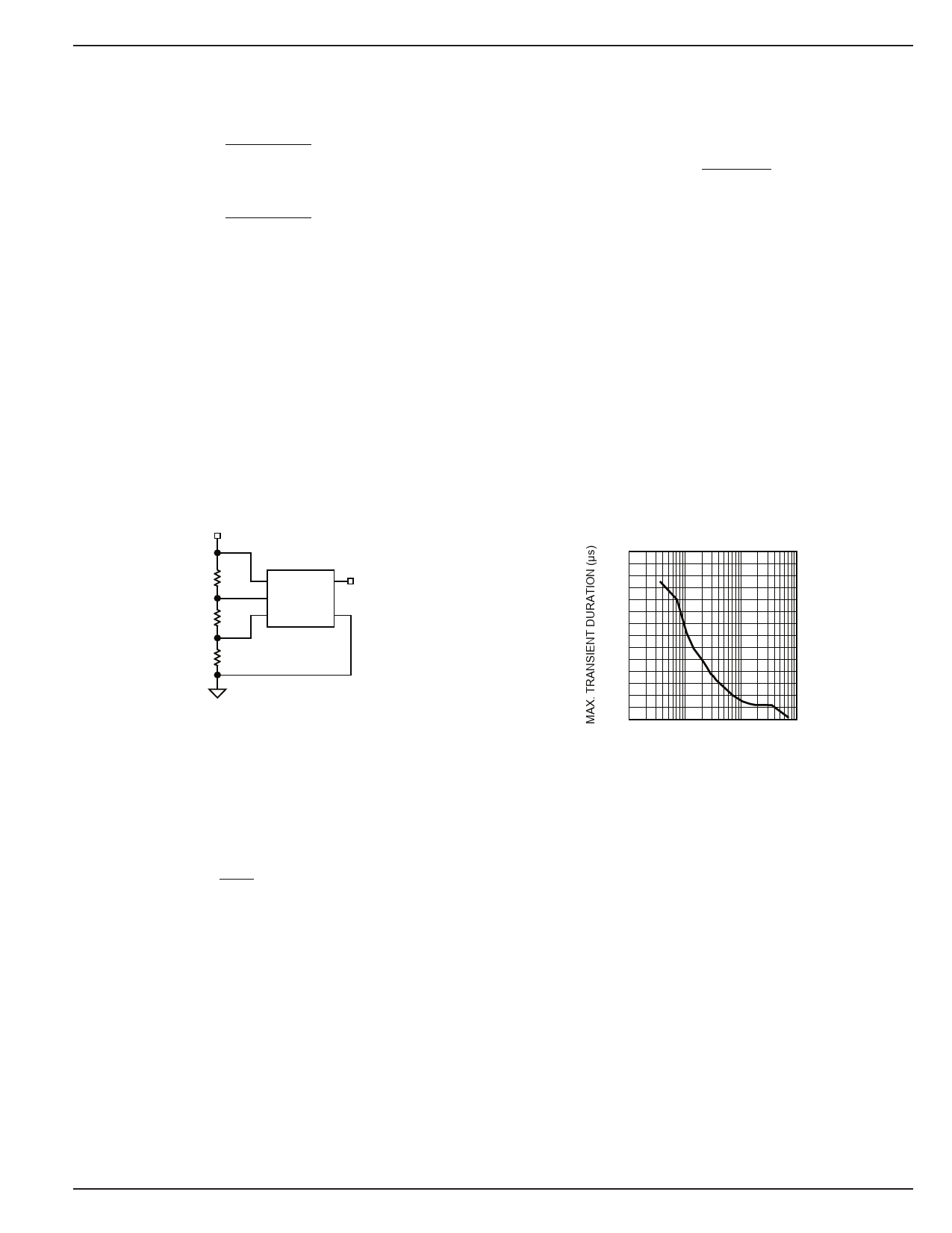
Input Transients
The MIC2779 is inherently immune to very short negative-
going “glitches.” Very brief transients may exceed the VBAT(lo)
threshold without tripping the output.
As shown in Figure 2, the narrower the transient, the deeper
the threshold overdrive that will be ignored by the MIC2779.
The graph represents the typical allowable transient duration
for a given amount of threshold overdrive that will not gener-
ate a reset.
Input Transient
Response
140
120
100
80
60
40
20
0
1
10
100
1000
RESET COMP. OVERDRIVE, VREF–VLTH (mV)
Figure 2. Input Transient Response
June 2000
5
MIC2779
Share Link: 