NCP1072P100G(2012) 查看數據表(PDF) - ON Semiconductor
零件编号
产品描述 (功能)
生产厂家
NCP1072P100G Datasheet PDF : 26 Pages
| |||
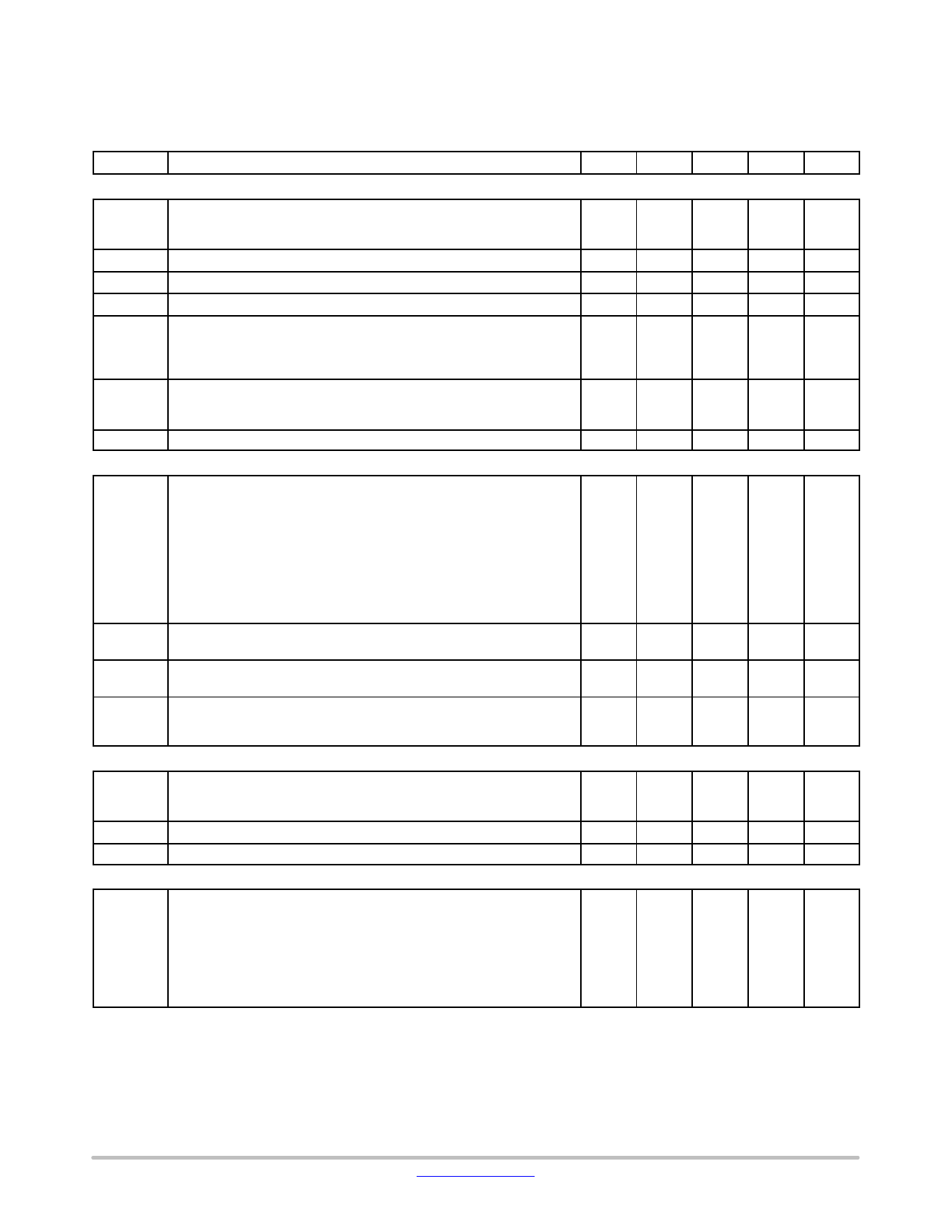
NCP1072, NCP1075
ELECTRICAL CHARACTERISTICS
(For typical values TJ = 25°C, for min/max values TJ = −40°C to +125°C, VCC = 8 V unless otherwise noted)
Symbol
Rating
Pin
Min
Typ
Max
Unit
INTERNAL START−UP CURRENT SOURCE
Istart2
High−voltage current source, VCC = 0 V
VCCTH VCC Transient level for Istart1 to Istart2 toggling point
CURRENT COMPARATOR
5
0.5
mA
1
−
2.2
−
V
IIPK
Maximum internal current setpoint at 50% duty cycle
FB pin open, NCP1072, TJ = 25°C
IIPK
Maximum internal current setpoint at 50% duty cycle
FB pin open, NCP1075, TJ = 25°C
IIPK(0)
Maximum internal current setpoint at beginning of switching cycle
FB pin open, NCP1072, TJ = 25°C
IIPKSW
Final switch current with a primary slope of 200 mA/ms,
FSW = 65 kHz, NCP1072 (Note 3)
IIPKSW
Final switch current with a primary slope of 200 mA/ms,
FSW = 100 kHz, NCP1072 (Note 3)
IIPKSW
Final switch current with a primary slope of 200mA/ms,
FSW = 130 kHz, NCP1072 (Notes 3 and 4)
IIPK(0)
Maximum internal current setpoint at beginning of switching cycle
FB pin open, NCP1075, TJ = 25°C
IIPKSW
Final switch current with a primary slope of 200 mA/ms,
FSW = 65 kHz, NCP1075 (Note 3)
IIPKSW
Final switch current with a primary slope of 200 mA/ms,
FSW = 100 kHz, NCP1075 (Note 3)
IIPKSW
Final switch current with a primary slope of 200 mA/ms,
FSW = 130 kHz, NCP1075 (Note 3)
TSS
Soft−start duration (guaranteed by design)
Tprop Propagation delay from current detection to drain OFF state
INTERNAL OSCILLATOR
−
250
mA
−
450
mA
−
254
282
310
mA
296
mA
293
mA
291
mA
−
467
508
549
mA
510
mA
500
mA
493
mA
−
1
ms
−
100
ns
fOSC
Oscillation frequency, 65 kHz version, TJ = 25°C (Note 5)
fOSC
Oscillation frequency, 100 kHz version, TJ = 25°C (Note 5)
fOSC
Oscillation frequency, 130 kHz version, TJ = 25°C (Notes 4 and 5)
fjitter
Frequency jittering in percentage of fOSC
fswing Jittering swing frequency
Dmax Maximum duty−cycle
FEEDBACK SECTION
−
59
65
71
kHz
−
90
100
110
kHz
−
117
130
143
kHz
−
±6
%
−
300
Hz
−
62
68
72
%
IFBfault FB current for which Fault is detected
4
IFB100% FB current for which internal current set−point is 100% (IIPK(0))
4
IFBfreeze FB current for which internal current setpoint is 97 mA (NCP1072) or
4
158 mA (NCP1075)
−35
mA
−44
mA
−80
mA
VFB(REF)
Equivalent pull−up voltage in linear regulation range
(Guaranteed by design)
4
3.3
V
RFB(up)
Equivalent feedback resistor in linear regulation range
(Guaranteed by design)
4
19.5
kW
3. The final switch current is: IIPK(0) / (Vin/LP + Sa) x Vin/LP + Vin/LP x tprop, with Sa the built−in slope compensation, Vin the input voltage, LP
the primary inductor in a flyback, and tprop the propagation delay..
4. NCP1072 130 kHz on demand only.
5. Oscillator frequency is measured with disabled jittering.
http://onsemi.com
5
Share Link: 