NCP5608 查看數據表(PDF) - ON Semiconductor
零件编号
产品描述 (功能)
生产厂家
NCP5608 Datasheet PDF : 16 Pages
| |||
NCP5608
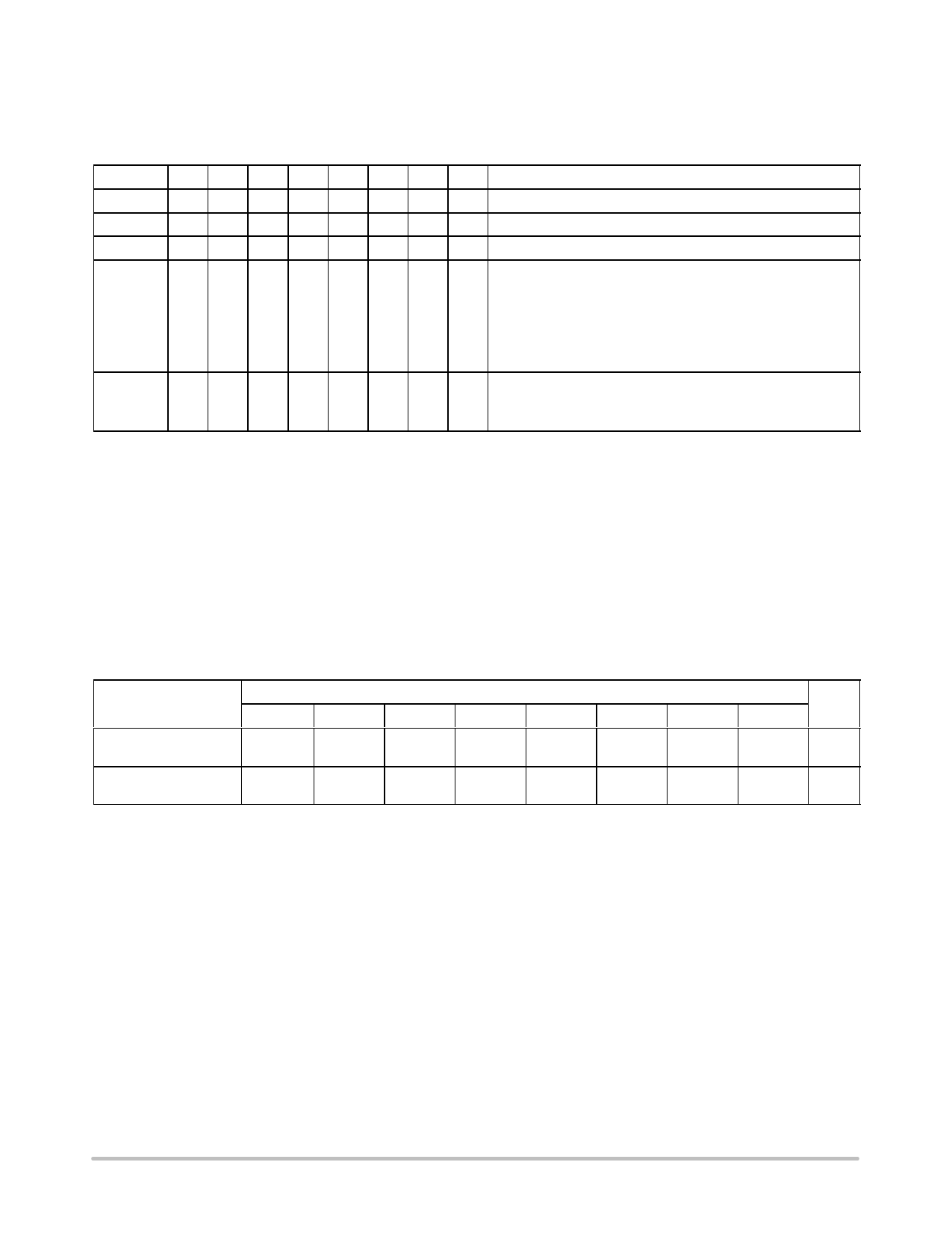
In order to improve the efficiency of the back light block
when three LED only are used, one can disconnect the
fourth LED by setting B6 = Low simultaneously with the
third byte (see Table 1).
Table 1. Programming Table
Byte
Byte #1
Byte #2
Byte #2
Byte #3
Byte #3
B7 B6 B5 B4 B3 B2 B1 B0
Comments
0
1
1
1
0
0
1
0 This is the I2C address
0
0
0
0
0
0
0
1 $01 = Select the Back Light internal register
0
0
0
0
0
0
1
0 $02 = Select the Power Flash internal register
1
0
0
X
X
X
X
X Assuming Byte #2 = $01, then:
Bits[0..4] = Back Light output current
Bit[5..6] = shall be Low
Bit[7] = control the fourth LED in the Back Light Block:
B7 = 0 ³ LED 4th disconnect
B7 = 1³ LED 4th connected
0
X
X
X
X
X
X
X Assuming Byte #2 = $02, then:
Bits[0..6] = Power Flash output current
Bit[7] = shall be Low
LED CURRENT CONTROL REGISTERS
The eight LED are split in two blocks:
Back Light Block:
Flash or High Power Block:
LED1 to LED4, current limited to 30 mA per
LED5 to LED8, current limited to 100 mA per
LED
LED
The programmed value of a given bank of LED is memorized into the appropriate registers. There is one register for each
set of LED:
PWRLED_BK[0..4]
PWRLED_FL[0..6]
Stores the Back Light output current.
Stores the Power Flash output current.
The total output current is limited to 500 mA, whatever be the configuration.
Table 2. Internal LED Current Control Register
Internal LEDs registers
Bit
Unit
B7
B6
B5
B4
B3
B2
B1
B0
PWRLED_BK[7..0]
BLED4
RFU
RFU
16
8.0
4.0
2.0
1.0
mA
(Note 12) (Note 11) (Note 11)
PWRLED_FL[7..0]
RFU
64
32
16
8.0
4.0
2.0
1.0
mA
(Note 11)
11. Reserved for future use.
12. Activates/deactivates LED4.
http://onsemi.com
9
Share Link: 