NIS5112(2006) 查看數據表(PDF) - ON Semiconductor
零件编号
产品描述 (功能)
生产厂家
NIS5112 Datasheet PDF : 9 Pages
| |||
NIS5112
There is an inherent delay in the turn on of the electronic
fuse, due to the method of gate drive used. The gate of the
power FET is charged through a high impedance resistor,
and from the time that the gate starts charging until the time
that it reaches its threshold voltage, there will be no
conduction. Once the gate reaches its threshold voltage, the
output current will begin a controlled ramp up phase.
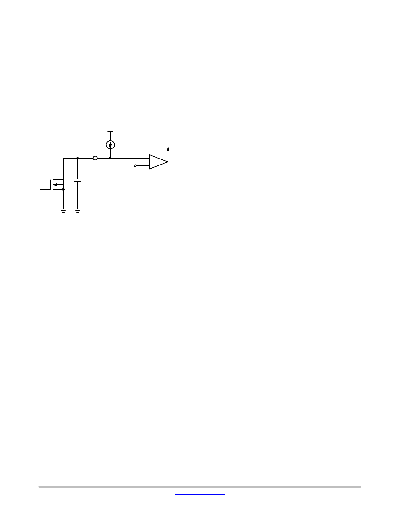
This delay will be added to any timing delay due to the
enable/timer circuit. Figure 8 shows a simplified diagram of
the enable/timer circuit.
Enable/
Timer
80 mA
+
Enabled
2.5 V
−
Thermal Protection Circuit
The temperature limit circuit senses the temperature of the
Power FET and removes the gate drive if the maximum level
is exceeded. The NIS5112 device has two different thermal
limit versions, auto−retry and latch off.
Auto−Retry Version
The device will shut down when the thermal limit
threshold is reached (TJ = 135°C, typical) and will not turn
back on until the die temperature reduces down to 95°C
(40°C hysteresis, typical). It will keep auto−retrying until
the fault condition is removed or power is turned−off.
Latch−Off Version
For the latch−off version, the device will shut down when
the thermal limit threshold is reached (TJ = 135°C, typical)
and will remain off until power is reset.
Figure 8. Simplified Schematic Diagram of the
Enable/Timer Circuit
http://onsemi.com
8
Share Link: 