NTE1559 查看數據表(PDF) - NTE Electronics
零件编号
产品描述 (功能)
生产厂家
NTE1559 Datasheet PDF : 2 Pages
| |||
Electrical Characteristics (Cont’d): (TA = +25°C, VCC = 13V, fc = 10.7MHz, fm = 400Hz,
f = 75kHz dev. unless otherwise specified)
Parameter
Symbol
Test Conditions
Min Typ Max Unit
Muting Bandwidth
BW(Mute) The sum of plus and minus side ∆fc’s for
V12 = 1.4V under 100dBµ if Vin
60 100 160 kHz
Muting Sensitivity
Vin(Mute) Without muting level control, Pin16 Open,
V12 = 1.4V
36 43 60 dBµ
Muting Sensitivity Control Range ∆Vin(Mute) Max Input Level for Muting Level Control
75 – – dBµ
Meter Driven Voltage (1)
V13–0 Vin = 0dBµ
–0–V
Meter Driven Voltage (2)
V13–70 Vin = 70dBµ
0.9 1.6 – V
Meter Driven Voltage (3)
V13–110 Vin = 110dBµ
4.5 5.5 – V
Recovered AF Voltage Attenuation VO(AM) Vin = 100dBµ, Pin15 Open, 13V supplied to 60 81 – dB
(for AM Band)
Pin15 via 4.7kΩ
Center–Meter Voltage
(For AM Band)
VCM(AM) Vin = 100dBµ, +150kHz detuned, the voltage –30 +7 +30 mV
difference of Pin7 and Pin10 with 13V sup-
plied to Pin15
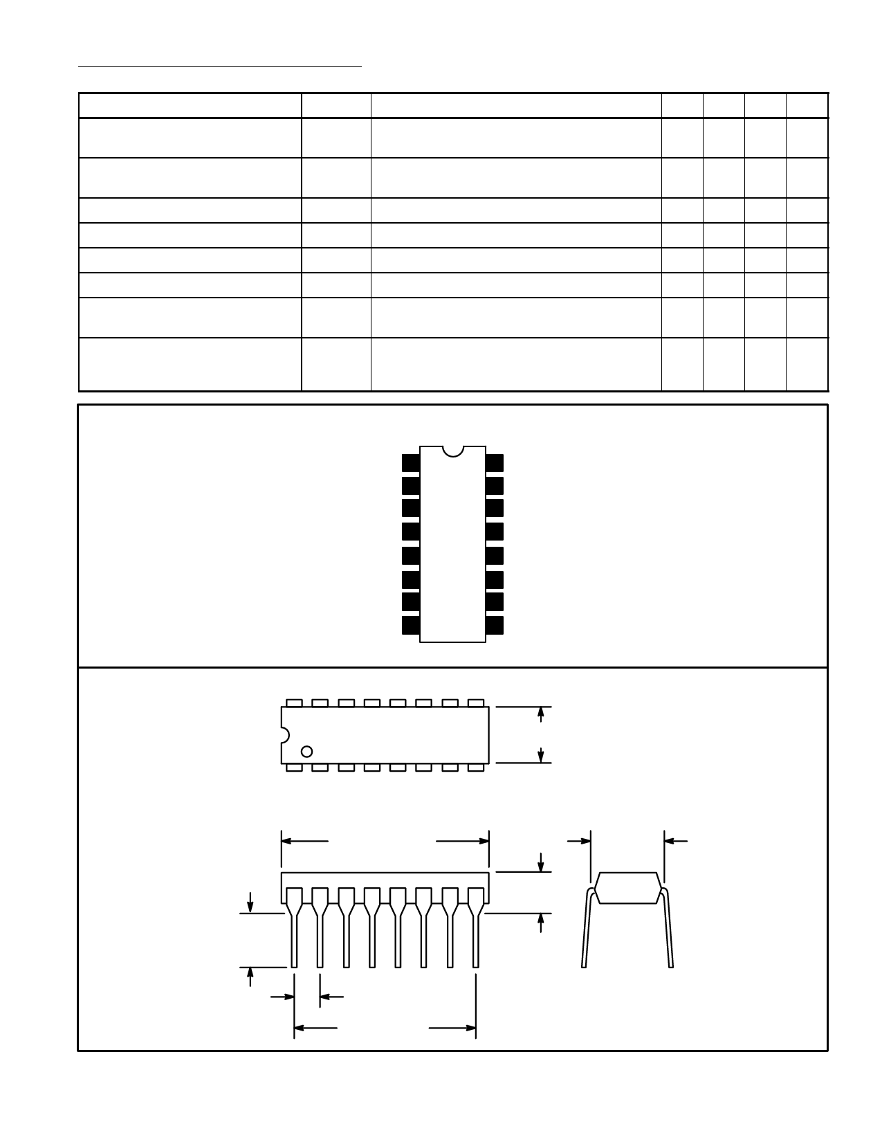
Pin Connection Diagram
1st IF Input 1
2nd IF Input 2
3rd IF Input 3
GND 4
Mute Control 5
Audio Amp Output 6
AFC Amp Output 7
Quadrature Tank 8
16 Level Control
15 Center Meter
14 GND
13 Signal Motor Drive
12 Mute Switch
11 VCC
10 Quadrature Tank
9 Quadrature Tank
16
9
.260 (6.6) Max
1
8
.245
(6.22)
Min
.785 (19.9)
Max
.100 (2.54)
.700 (17.7)
.200 (5.08)
Max
.300
(7.62)
Share Link: 