NTE851 查看數據表(PDF) - NTE Electronics
零件编号
产品描述 (功能)
生产厂家
NTE851 Datasheet PDF : 2 Pages
| |||
Electrical Characteristics: (TA = +25°C, V+ = 5V, V– = 0 unless otherwise specified)
Parameter
Symbol
Test Conditions
Min Typ Max Unit
Supply Current
I+ Pin1 and Pin2
30 60 90 mA
UHF Bandswitch Input Voltage
VHF Bandswitch Input Voltage
UHF Bandswitch Input Current
VHF Bandswitch Input Current
UHF Sensitivity Level Input Voltage
VHF Sensitivity Level Input Voltage
Output Voltage
Output Voltage Rise and Fall Time
VBH High Level
2.4 –
VBL Low Level
–
–
IBH VBH = 20V
–
–
IBL VBL = 0
–
–
VIN(U) fIN = 450 to 950MHz, fOUT = fIN/256 –
–
VIN(V) fIN = 90 to 275MHz, fOUT = fIN/64
VO Pin4 or Pin5
0.65 1.0
tr, tf
– 70
–
V
0.8 V
0.5 mA
–1 mA
80 mVrms
mVrms
– VP–P
–
ns
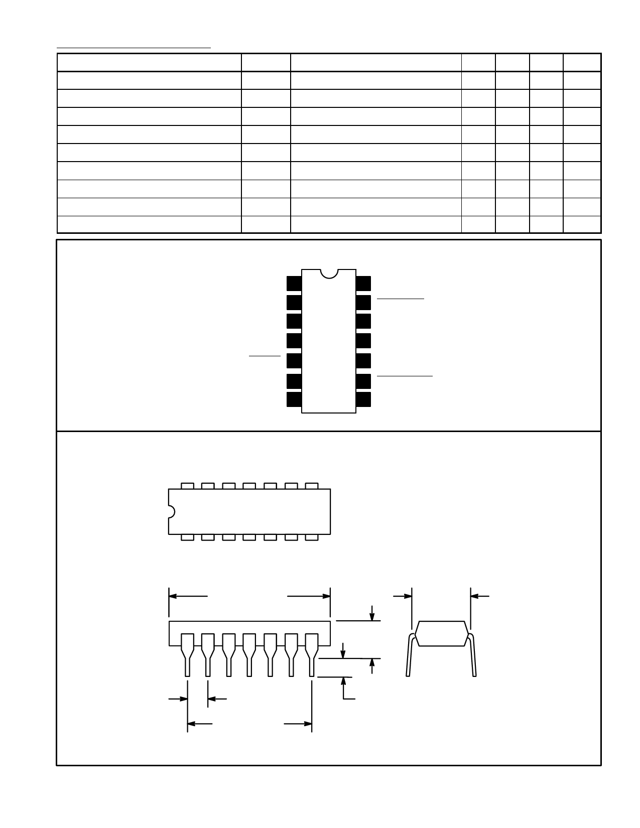
Pin Connection Diagram
V(+) 1 1
V(+) 2 2
Bandswitch Input 3
Output 4
Output 5
N.C. 6
V(–) 1 7
14 VHF Input
13 VHF Input
12 N.C.
11 N.C.
10 UHF Output
9 UHF Output
8 V(–) 2
14
8
1
7
.785 (19.95)
Max
.200 (5.08)
Max
.300
(7.62)
.100 (2.45)
.600 (15.24)
.099 (2.5) Min
Share Link: 