PCA9500 查看數據表(PDF) - Philips Electronics
零件编号
产品描述 (功能)
生产厂家
PCA9500 Datasheet PDF : 23 Pages
| |||
Philips Semiconductors
8-bit I2C and SMBus I/O port with 2-kbit EEPROM
Product data sheet
PCA9500
Read operations
PCA9500 read operations are initiated in an identical manner to
write operations with the exception that the memory slave address’
R/W bit is set to a one. There are three types of read operations;
current address, random and sequential.
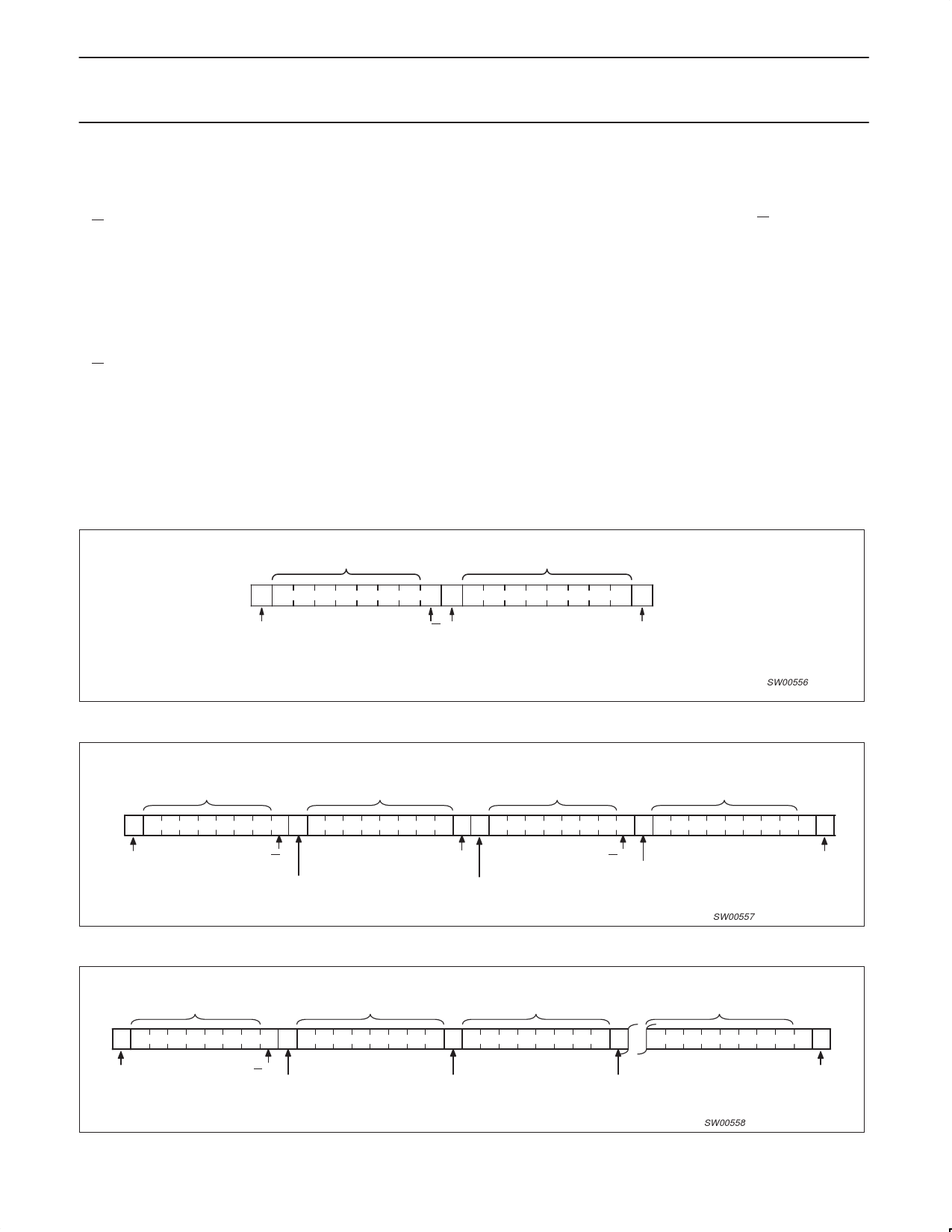
Current Address Read (see Figure 11)
The PCA9500 contains an internal address counter that increments
after each read or write access, as a result if the last word accessed
was at address n then the address counter contains the address
n+1.
When the PCA9500 receives its memory slave address with the
R/W bit set to one it issues an acknowledge and uses the next eight
clocks to transmit the data contained at the address stored in the
address counter. The master ceases the transmission by issuing the
stop condition after the eighth bit. There is no ninth clock cycle for
the acknowledge.
Random Read (see Figure 12)
The PCA9500’s random read mode allows the address to be read
from to be specified by the master. This is done by performing a
dummy write to set the address counter to the location to be read.
The master must perform a byte write to the address location to be
read, but instead of transmitting the data after receiving the
acknowledge from the PCA9500 the master reissues the start
condition and memory slave address with the R/W bit set to one.
The PCA9500 will then transmit an acknowledge and use the next
eight clock cycles to transmit the data contained in the addressed
location. The master ceases the transmission by issuing the stop
condition after the eighth bit, omitting the ninth clock cycle
acknowledge.
Sequential Read (see Figure 13)
The PCA9500 sequential read is an extension of either the current
address read or random read. If the master doesn’t issue a stop
condition after it has received the eighth data bit, but instead issues
an acknowledge, the PCA9500 will increment the address counter
and use the next eight cycles to transmit the data from that location.
The master can continue this process to read the contents of the
entire memory. Upon reaching address 255 the counter will return to
address 0 and continue transmitting data until a stop condition is
received. The master ceases the transmission by issuing the stop
condition after the eighth bit, omitting the ninth clock cycle
acknowledge.
SLAVE ADDRESS (MEMORY)
DATA FROM MEMORY
SDA S 1 0 1 0 A2 A1 A0 1 A
START CONDITION
R/W ACKNOWLEDGE
FROM SLAVE
P
STOP
CONDITION
Figure 11. Current Address Read
SW00556
SLAVE ADDRESS (MEMORY)
WORD ADDRESS
SLAVE ADDRESS (MEMORY)
DATA FROM MEMORY
SDA S 1 0 1 0 A2 A1 A0 0 A
A S 1 0 1 0 A2 A1 A0 1 A
START
CONDITION
R/W
ACKNOWLEDGE
FROM SLAVE
ACKNOWLEDGE
FROM SLAVE
START
CONDITION
Figure 12. Random Read
R/W
ACKNOWLEDGE
FROM SLAVE
SW00557
P
STOP
CONDITION
SLAVE ADDRESS (MEMORY)
DATA FROM MEMORY
DATA FROM MEMORY
DATA FROM MEMORY
SDA S 1 0 1 0 A2 A1 A0 1 A
DATA n
START CONDITION
R/W
ACKNOWLEDGE
FROM SLAVE
A
DATA n+1
ACKNOWLEDGE
FROM MASTER
Figure 13. Sequential Read
A
DATA n+X
ACKNOWLEDGE
FROM MASTER
SW00558
P
STOP
CONDITION
2004 Sep 30
8
Share Link: 